
 TechyTron
Voltage Explorer Kit
SKU: TT-SE-05-01
₹1,098.50
Includes 18% GST
Earn 10 reward points per unit. How rewards work
Measure voltage and discover how a resistor divider works. Classes 5-6 · Ages 10–12. Complete electronics kit with an illustrated guide.
Delivery options
Courier from ₹79.00 per order · Free above ₹999.00
Product description
Classes 5-6, typical ages 10–12. Age ranges vary by learner. Guided low-voltage electronics.
Activity engagement
45–60 minutes. Explore 5–10 min · Build 15–20 min · Test and discuss 25–30 min. Estimated time for building, testing and discussion.
What you need
No computer required. An adult helps inspect connections.
Included components
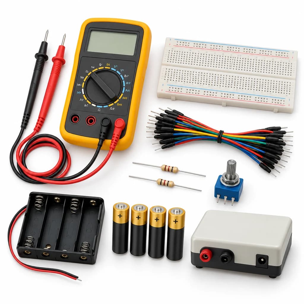
- Small Breadboard / Mini Solderless Board - 400 points — 1 breadboard
- Jumper Wire Combo - Male to Male, Male to Female and Female to Female Breadboard Connecting Wires (10 Qty Each) — 1 set
- Illustrated Activity Guide and Observation Sheets — 1 set
- Fitted Headers and Labelled Connection Leads — 1 set
- 4 CELL AA BATTERY HOLDER WITH SWITCH / COVER — 1 holder
- AA BATTERY — 4 battery (individual units)
- Regulated 5 V Power Supply with Short-Circuit Protection — 1 power supply
- DT9205A Digital Multimeter with Probes and Battery — 1 multimeter
- 10 K POTENTIOMETER — 1 potentiometer
- 10K Ω 1/4 Watts (10 PCS) — 2 resistor (individual units)
What you learn
- Voltage is measured across two points; resistance is measured with power disconnected.
- Equal series resistors divide a voltage approximately in half.
- A potentiometer produces an adjustable voltage.
Connection guide
- Meter black lead → COM; red lead → V/ohm socket. Select DC volts, never the current socket for this activity.
- Two 10 kOhm resistors in series: regulated +5 V → R1 → midpoint → R2 → GND.
- Potentiometer outer pins → +5 V and GND; centre wiper is the adjustable output.
Steps to make it
- Disconnect all power and identify the supplied part labels and pinouts before wiring.
- With the supply disconnected, measure each resistor on the ohms range and write its value.
- Build the two-resistor divider. Select DC volts before connecting the supply.
- Measure across +5 V/GND, then midpoint/GND; compare midpoint voltage with half the measured supply.
- Disconnect power, replace the divider with the potentiometer, reconnect and measure its wiper voltage at five positions.
- Return the supply switch to OFF and remove the probes.
Test challenge
Predict the midpoint voltage, measure it three times, then compare the five potentiometer settings.
Observation task
Table: resistor values, supply voltage, predicted midpoint, measured midpoint, and potentiometer position.
Expected result
The equal-resistor midpoint is near half the supply; the wiper moves between near-zero and near-supply voltage.
If it does not work
Check meter mode and sockets first. A floating midpoint or broken breadboard rail gives inconsistent readings.
Try next
Use the potentiometer as one divider arm and draw the measured voltage curve.
Use and supervision
Use only the supplied low-voltage DC parts. Disconnect power before rewiring; check polarity and labelled pinouts. No soldering or exposed mains connections. Adult guidance is recommended.
How this experiment works
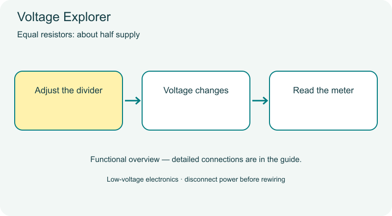
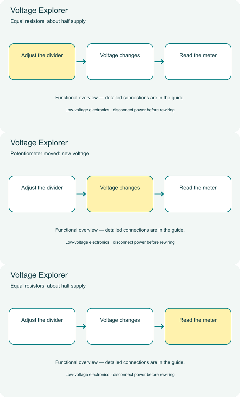
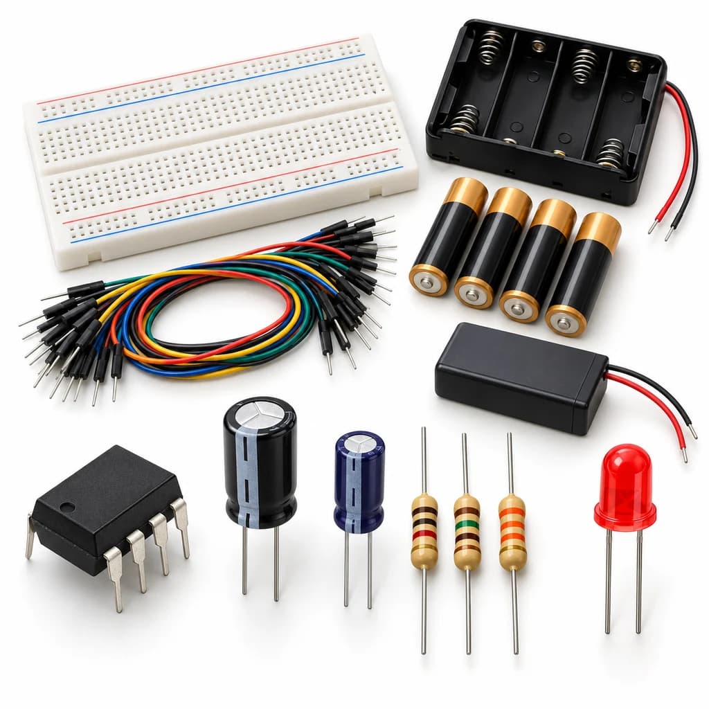
Cover illustrations show component types. Functional animations explain principles and are not recorded prototype tests. Follow the supplied connection labels and pinouts.
Customer feedback
Reviews
No published reviews yet. Be the first to share useful feedback.
Shop Related in this category
Related in this category
9 catalogue productsTechyTron TechyTron
Capacitor Countdown Kit
₹537.50Earn 5 points TechyTron
Heat Sense Alarm Kit
₹631.00Earn 6 points TechyTron
Rain Drop Alarm Kit
₹637.00Earn 6 points TechyTron
Soil Moisture Signal Kit
₹608.00Earn 6 points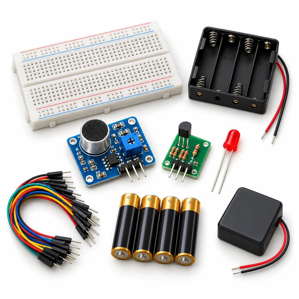 TechyTron
Sound Trigger Light Kit
₹609.00Earn 6 points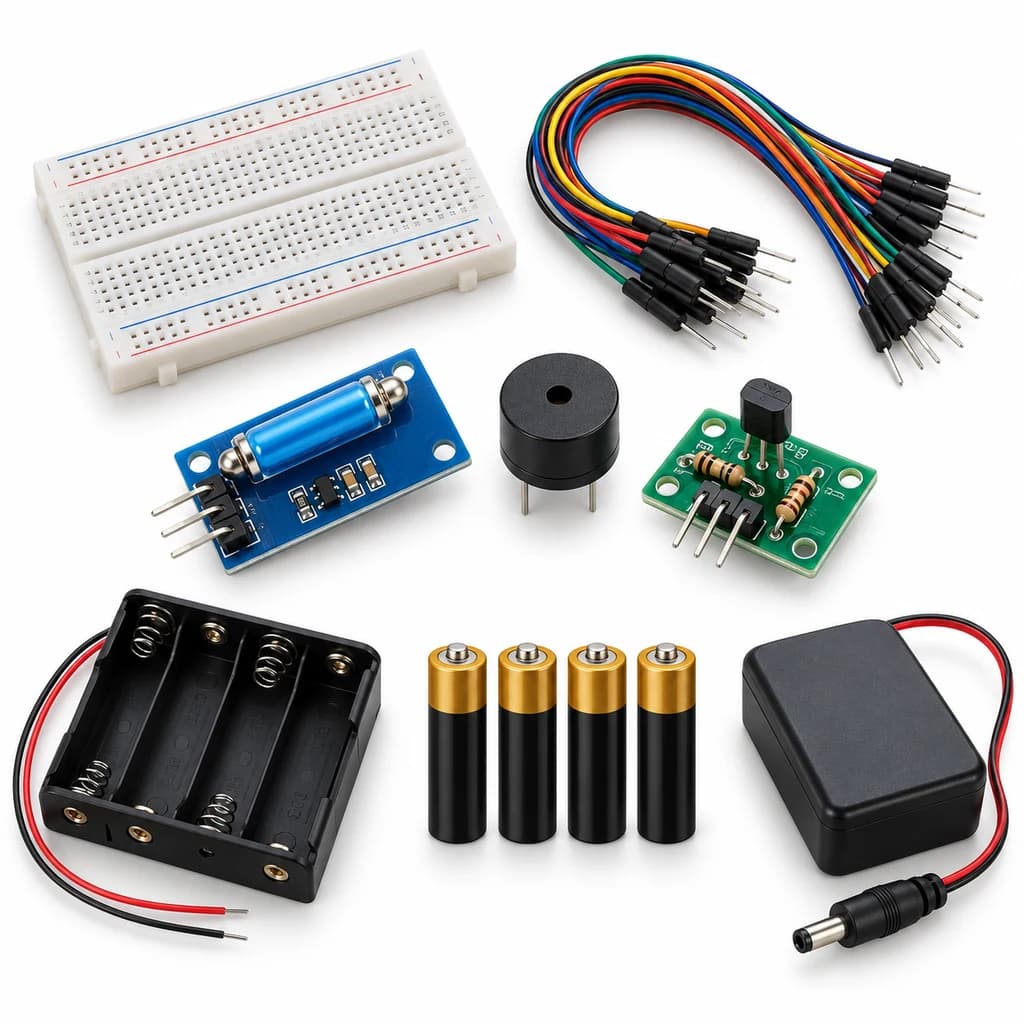 TechyTron
Tilt Alarm Lab Kit
₹631.00Earn 6 points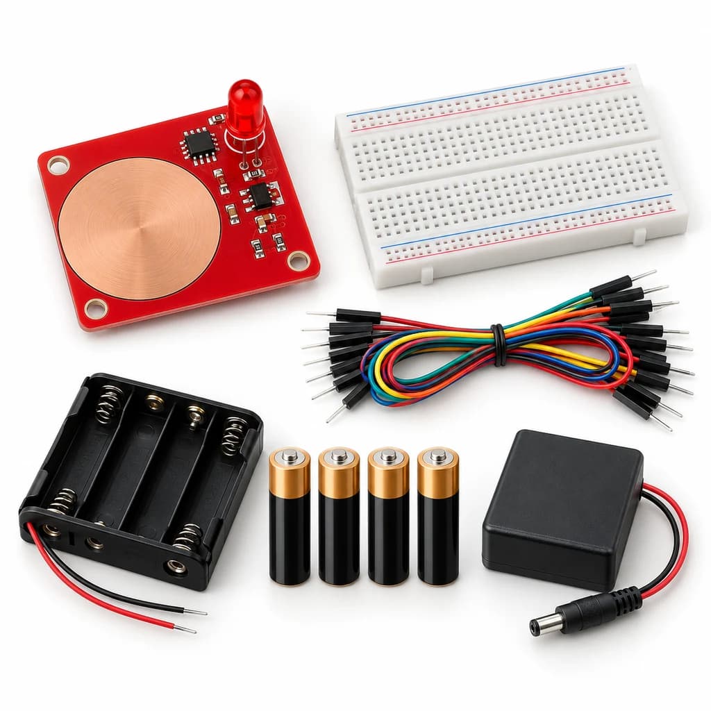 TechyTron
Touch Pad Light Kit
₹519.00Earn 5 points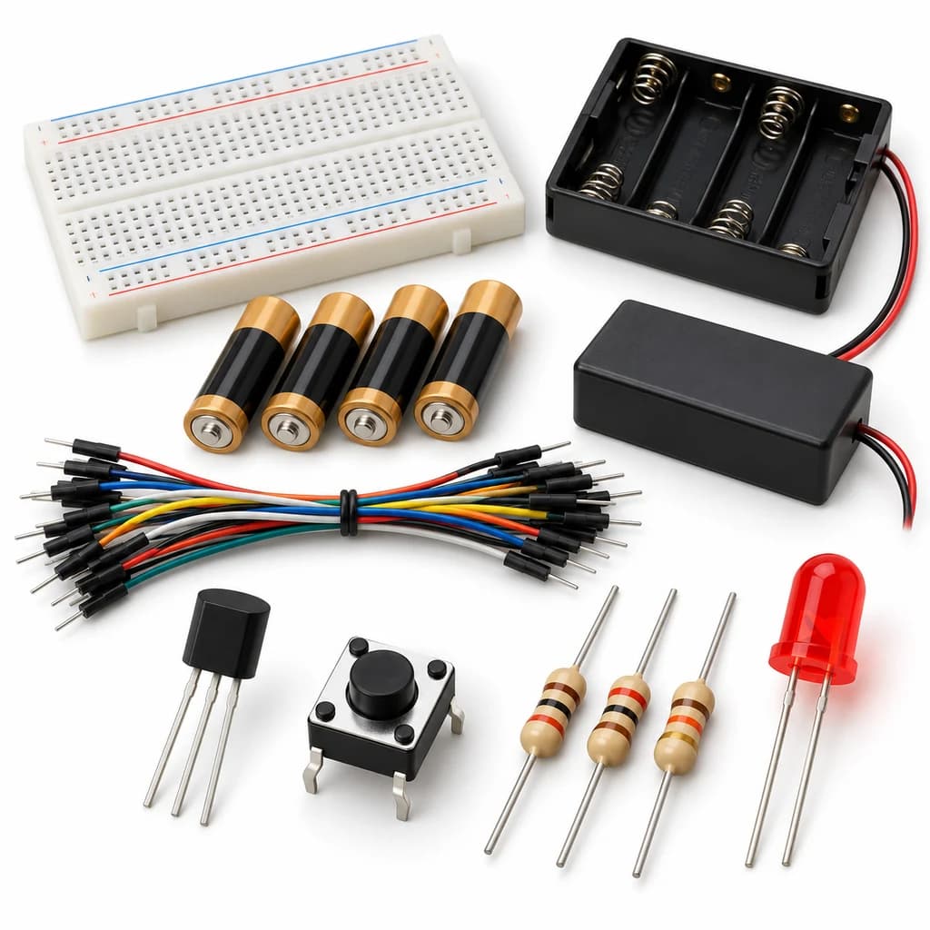 TechyTron
Transistor Light Switch Kit
₹521.50Earn 5 pointsShop Related by product name
Related by product name
10 catalogue products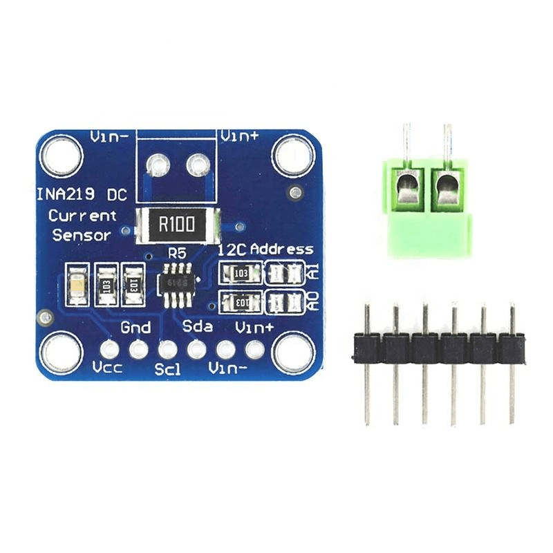 Current, Voltage & Energy Sensors
CJMCU-219 INA219 I2C Interface Zero Drift Bi-directional Current / Power Supply Monitoring Module
₹99.00 Semiconductors & Prototyping Components
OB2269AP Current Mode PWM Controller IC - DIP-8 Package
₹19.00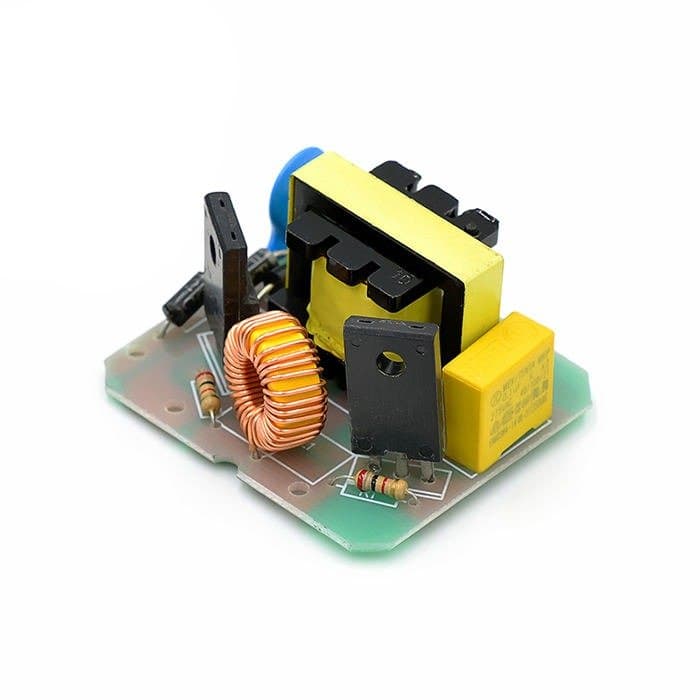 Voltage Regulators & DC-DC Converters
12V DC to 220V AC 40W Step-Up Inverter Booster Module
₹194.50Earn 1 points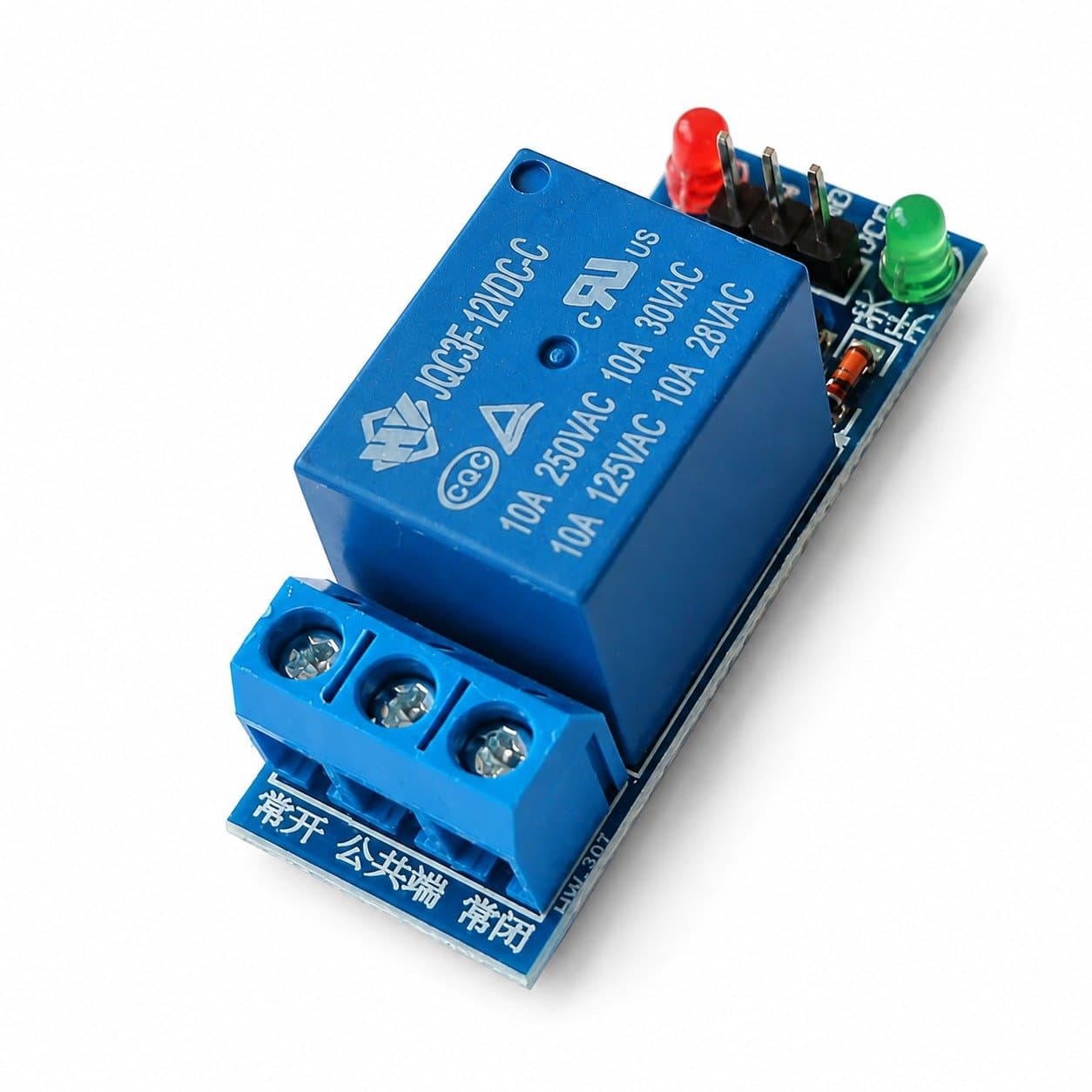 Relay Modules (Single Channel)
12V Single Channel Relay Module
₹54.50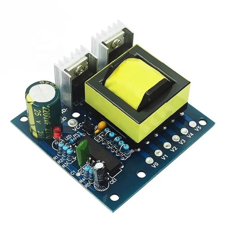 Inverter Modules
150W DC 12V to AC 110V/220V Inverter Boost Module
₹566.50Earn 5 points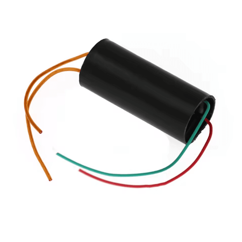 High Voltage Generator Modules
3-6V 400KV High Voltage Generator Boost Module
₹163.00Earn 1 points Batteries, Power Supplies & Accessories
3S 10A Lithium Battery Protection BMS Module for 11.1V NMC cells
₹71.00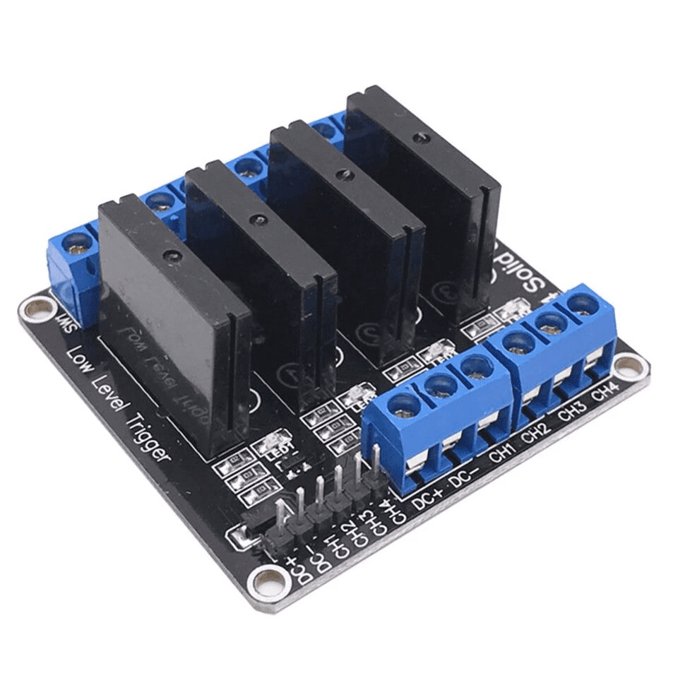 Relays
4 Channel DC 5V Solid State SSR Relay Module
₹531.00Earn 5 points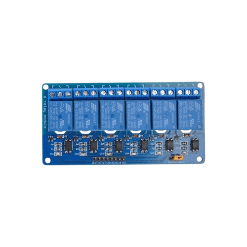 Relay Modules (Multi-Channel)
5V 6 Channel Relay Module with OptoCoupler
₹307.00Earn 3 points Other Relays