
 TechyTron
Capacitor Countdown Kit
SKU: TT-SE-05-02
₹537.50
Includes 18% GST
Earn 5 reward points per unit. How rewards work
Build a one-shot electronic timer with a 555 chip. Classes 5-6 · Ages 10–12. Complete electronics kit with an illustrated guide.
Delivery options
Courier from ₹79.00 per order · Free above ₹999.00
Product description
Classes 5-6, typical ages 10–12. Age ranges vary by learner. Guided low-voltage electronics.
Activity engagement
60–90 minutes. Explore 10–15 min · Build 20–30 min · Test and discuss 30–45 min. Estimated time for building, testing and discussion.
What you need
No computer required. An adult helps inspect connections.
Included components
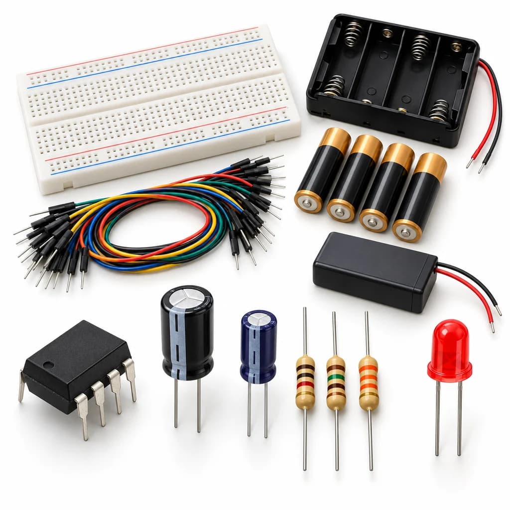
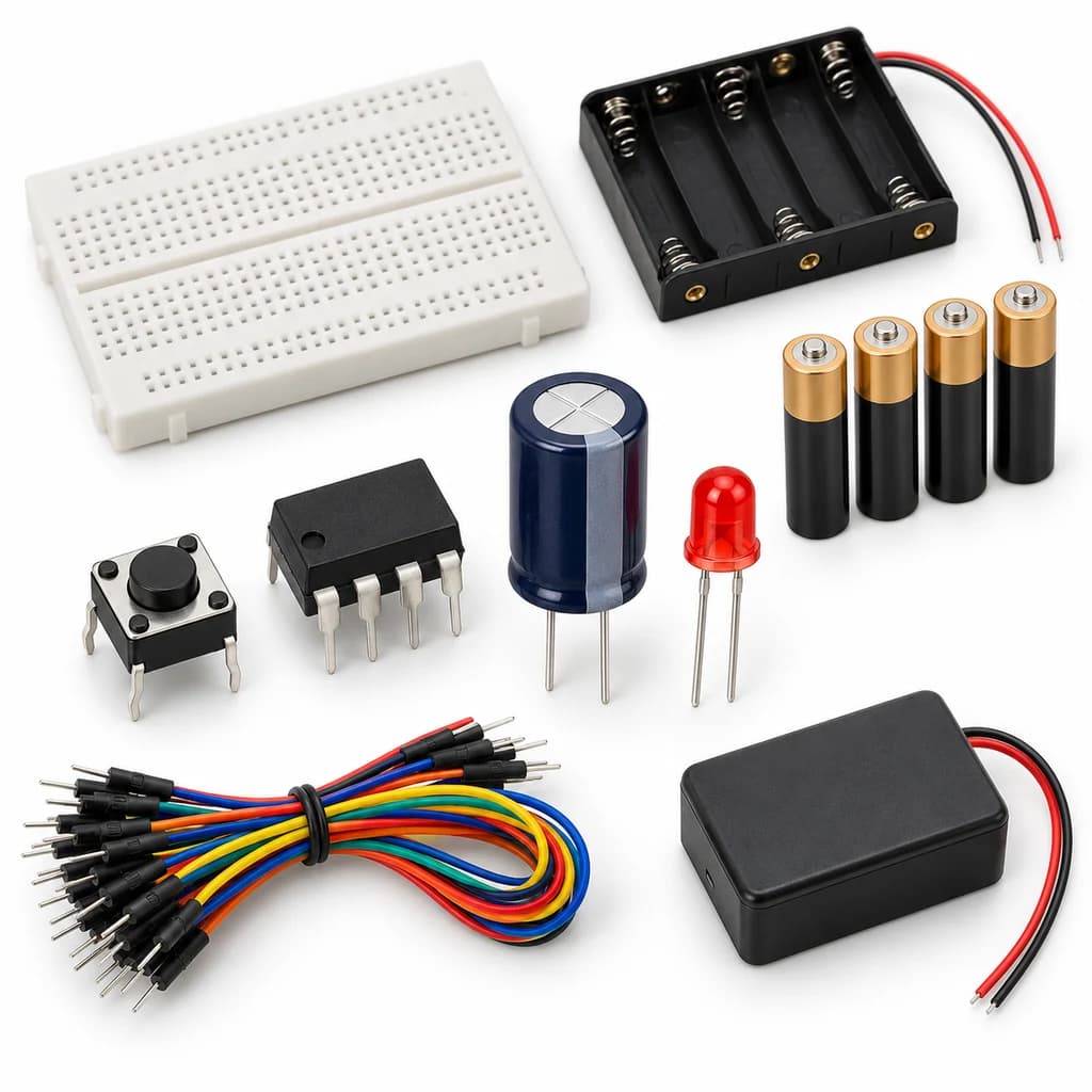
- Small Breadboard / Mini Solderless Board - 400 points — 1 breadboard
- Jumper Wire Combo - Male to Male, Male to Female and Female to Female Breadboard Connecting Wires (10 Qty Each) — 1 set
- Illustrated Activity Guide and Observation Sheets — 1 set
- Fitted Headers and Labelled Connection Leads — 1 set
- 4 CELL AA BATTERY HOLDER WITH SWITCH / COVER — 1 holder
- AA BATTERY — 4 battery (individual units)
- Regulated 5 V Power Supply with Short-Circuit Protection — 1 power supply
- 555 Timer IC (LM555 / NE555 / SE555) - 8 Pin DIP Package — 1 IC
- Tactile Push Button Switch 12x12x8mm 4-Pin — 1 button
- 100 µF CAPACITOR (5 PCS) — 1 capacitor
- 100K Ω 1/4 Watts (10 PCS) — 1 resistor
- 10K Ω 1/4 Watts (10 PCS) — 1 resistor
- 5mm LED - Red Color — 1 LED
- 330 Ω 1/4 Watts (10 PCS) — 1 resistor
- 0.01 µF CAPACITOR (5 PCS) — 1 capacitor
- 0.1 µF CAPACITOR (5 PCS) — 1 capacitor
What you learn
- A capacitor stores charge and changes voltage over time.
- A 555 monostable makes a single pulse after a trigger.
- The approximate pulse length is 1.1 × R × C.
Connection guide
- NE555 pin 1 → GND; 8 and 4 → +5 V. Add 100 nF across pins 8/1 and 10 nF from pin 5 to GND.
- Pins 6 and 7 → timing node; 100 kOhm from +5 V to that node; 100 uF capacitor positive to node and negative to GND.
- Pin 2 → +5 V through 10 kOhm; push button from pin 2 to GND. Pin 3 → 330 Ohm → LED anode; cathode → GND.
Steps to make it
- Disconnect all power and identify the supplied part labels and pinouts before wiring.
- Place the DIP chip across the breadboard centre gap; locate pin 1 from its notch/dot using the connection card.
- Connect the supply and control pins, then the timing network, checking electrolytic capacitor polarity.
- Add the trigger button and current-limited LED. Ask an adult to inspect the rails.
- Apply regulated 5 V, tap and release the button, and time the LED pulse with a clock.
- Repeat five trials, allowing the LED to go out before triggering again.
Test challenge
Compare the measured LED-on time with 1.1 × 100000 × 0.0001, approximately 11 seconds.
Observation task
Five pulse lengths, mean time, predicted time, and percentage difference.
Expected result
A short button press produces a much longer LED pulse; capacitor tolerance means timing is approximate.
If it does not work
Switch off and check pin numbering, pin 4 at +5 V, capacitor polarity and the trigger pull-up. Do not hold the button down while timing.
Try next
Explain why a larger timing resistor would lengthen the pulse.
Use and supervision
Use only the supplied low-voltage DC parts. Disconnect power before rewiring; check polarity and labelled pinouts. No soldering or exposed mains connections. Adult guidance is recommended.
How this experiment works
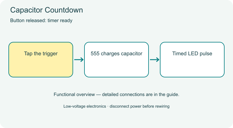
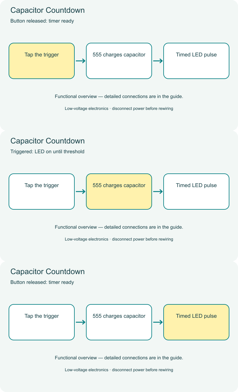
Cover illustrations show component types. Functional animations explain principles and are not recorded prototype tests. Follow the supplied connection labels and pinouts.
Customer feedback
Reviews
No published reviews yet. Be the first to share useful feedback.
Shop Related in this category
Related in this category
9 catalogue productsTechyTron TechyTron
Heat Sense Alarm Kit
₹631.00Earn 6 points TechyTron
Rain Drop Alarm Kit
₹637.00Earn 6 points TechyTron
Soil Moisture Signal Kit
₹608.00Earn 6 points TechyTron
Sound Trigger Light Kit
₹609.00Earn 6 points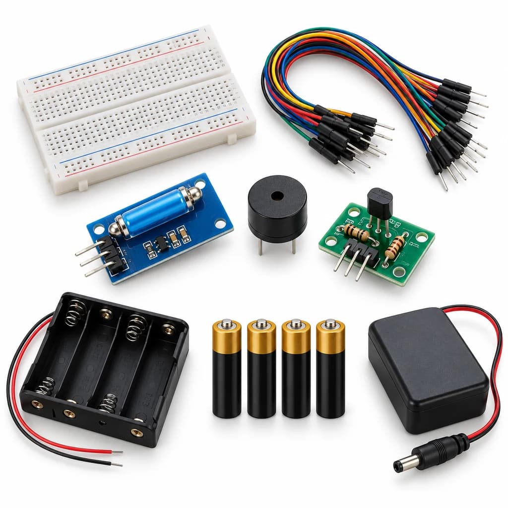 TechyTron
Tilt Alarm Lab Kit
₹631.00Earn 6 points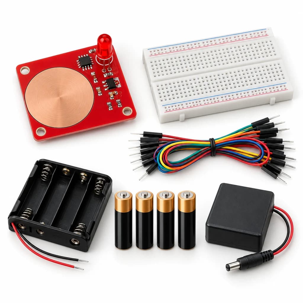 TechyTron
Touch Pad Light Kit
₹519.00Earn 5 points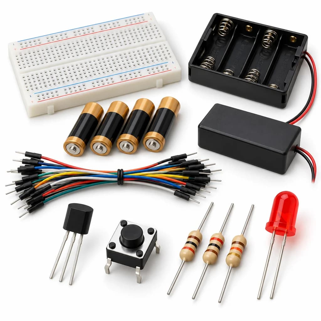 TechyTron
Transistor Light Switch Kit
₹521.50Earn 5 points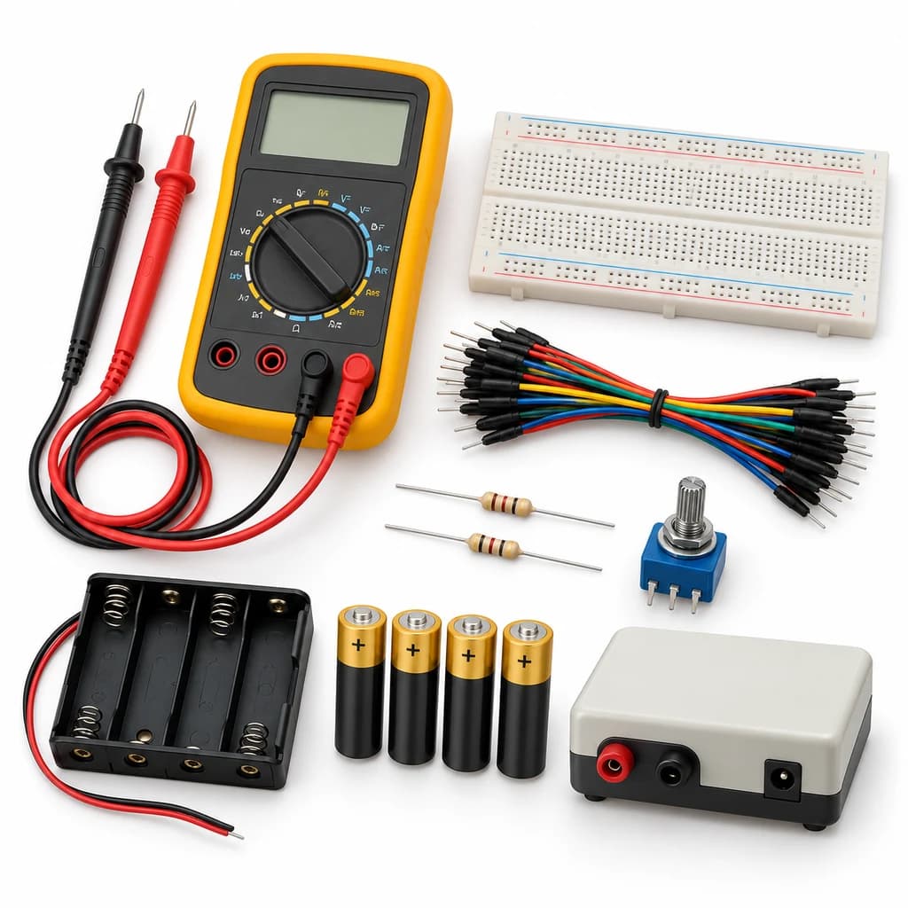 TechyTron
Voltage Explorer Kit
₹1,098.50Earn 10 pointsShop Related by product name
Related by product name
10 catalogue products Semiconductors & Prototyping Components
PCB for LM2596S Buck Converter Module - Fixed Voltage Version 5V/3.3V
₹19.000.001 µF CAPACITOR (5 PCS)
₹10.000.01 µF CAPACITOR (5 PCS)
₹10.000.1 µF CAPACITOR (5 PCS)
₹10.00 Capacitors (Ceramic)
0.5nF / 500pF 50V 0805 X7R SMD Capacitor (Pack of 20 Pieces)
₹41.50 Capacitors (Ceramic)
0.82uF / 820nF 50V 0805 X7R SMD Capacitor (Pack of 20 Pieces)
₹41.50 Mechanical Tools