
 TechyTron
Blink Beat Kit
SKU: TT-SE-05-03
₹535.50
Includes 18% GST
Earn 5 reward points per unit. How rewards work
Make an adjustable-rate LED oscillator without a computer. Classes 5-6 · Ages 10–12. Complete electronics kit with an illustrated guide.
Delivery options
Courier from ₹79.00 per order · Free above ₹999.00
Product description
Classes 5-6, typical ages 10–12. Age ranges vary by learner. Guided low-voltage electronics.
Activity engagement
60–90 minutes. Explore 10–15 min · Build 20–30 min · Test and discuss 30–45 min. Estimated time for building, testing and discussion.
What you need
No computer required. An adult helps inspect connections.
Included components
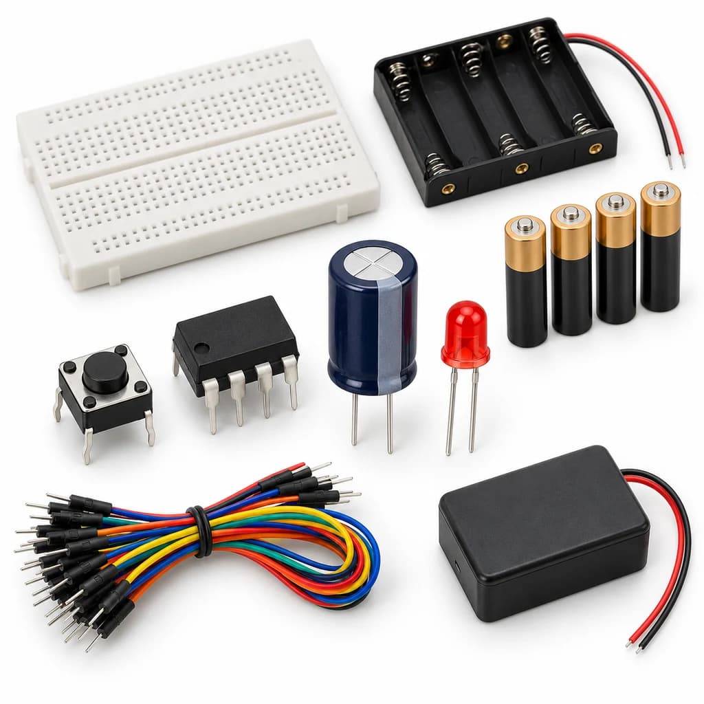
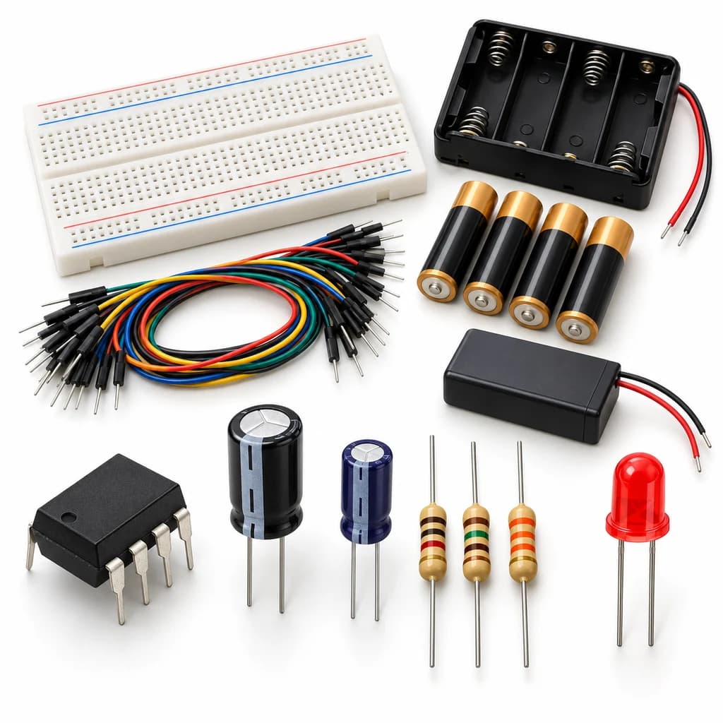
- Small Breadboard / Mini Solderless Board - 400 points — 1 breadboard
- Jumper Wire Combo - Male to Male, Male to Female and Female to Female Breadboard Connecting Wires (10 Qty Each) — 1 set
- Illustrated Activity Guide and Observation Sheets — 1 set
- Fitted Headers and Labelled Connection Leads — 1 set
- 4 CELL AA BATTERY HOLDER WITH SWITCH / COVER — 1 holder
- AA BATTERY — 4 battery (individual units)
- Regulated 5 V Power Supply with Short-Circuit Protection — 1 power supply
- 555 Timer IC (LM555 / NE555 / SE555) - 8 Pin DIP Package — 1 IC
- 10 µF CAPACITOR (5 PCS) — 1 capacitor
- 100 µF CAPACITOR (5 PCS) — 1 capacitor
- 1K Ω 1/4 Watts (10 PCS) — 1 resistor
- 47K Ω 1/4 Watts (10 PCS) — 1 resistor
- 5mm LED - Red Color — 1 LED
- 330 Ω 1/4 Watts (10 PCS) — 1 resistor
- 0.01 µF CAPACITOR (5 PCS) — 1 capacitor
- 0.1 µF CAPACITOR (5 PCS) — 1 capacitor
What you learn
- An oscillator repeats without repeated button presses.
- Resistance and capacitance set the flashing period.
- Frequency is cycles per second, the inverse of period.
Connection guide
- NE555 pins 1 → GND; 8 and 4 → +5 V; 100 nF supply decoupling and 10 nF pin 5 → GND.
- Tie pins 2 and 6 together. Connect 1 kOhm from +5 V to pin 7 and 47 kOhm from pin 7 to pins 2/6.
- Timing capacitor positive → pins 2/6 and negative → GND. Pin 3 → 330 Ohm → LED → GND.
Steps to make it
- Disconnect all power and identify the supplied part labels and pinouts before wiring.
- Identify the chip pins, then build the supply and resistor network with power off.
- Fit the 10 uF timing capacitor with the correct polarity and add the LED branch.
- Power on and count ten flashes; divide the elapsed time by ten to estimate period.
- Switch off, discharge the timing capacitor through the resistor network, and replace 10 uF with 100 uF.
- Repeat the count, compare periods and disconnect power.
Test challenge
Does increasing capacitance tenfold increase the period by approximately tenfold?
Observation task
Capacitance, time for ten cycles, period and calculated frequency.
Expected result
The larger capacitor produces slower flashes; nominal periods are about 0.66 s and 6.6 s.
If it does not work
Check that pins 2 and 6 are joined and pin 7 is between the two resistors; confirm both capacitors are individual parts, not whole packs.
Try next
Use T ≈ 0.693 × (R1 + 2R2) × C to compare predicted and measured periods.
Use and supervision
Use only the supplied low-voltage DC parts. Disconnect power before rewiring; check polarity and labelled pinouts. No soldering or exposed mains connections. Adult guidance is recommended.
How this experiment works
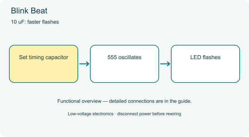
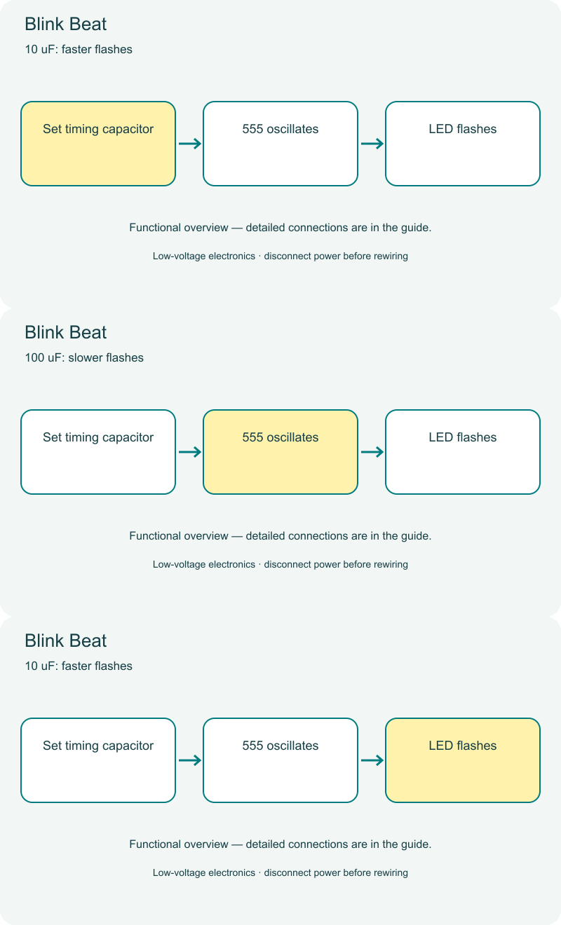
Cover illustrations show component types. Functional animations explain principles and are not recorded prototype tests. Follow the supplied connection labels and pinouts.
Customer feedback
Reviews
No published reviews yet. Be the first to share useful feedback.
Shop Related in this category
Related in this category
9 catalogue productsTechyTron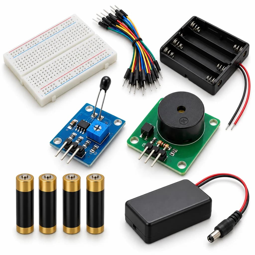 TechyTron
Heat Sense Alarm Kit
₹631.00Earn 6 points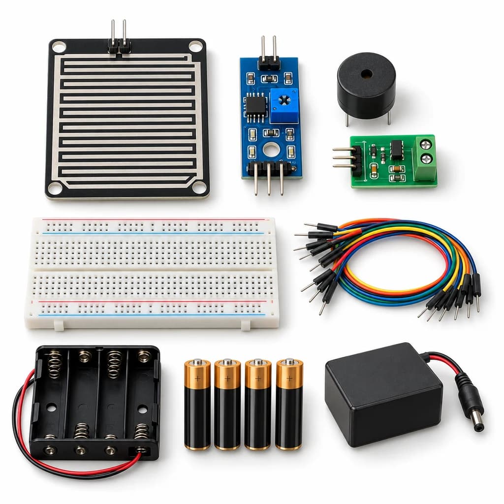 TechyTron
Rain Drop Alarm Kit
₹637.00Earn 6 points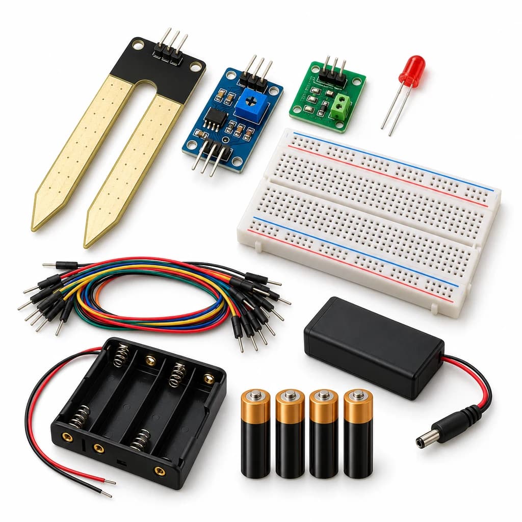 TechyTron
Soil Moisture Signal Kit
₹608.00Earn 6 points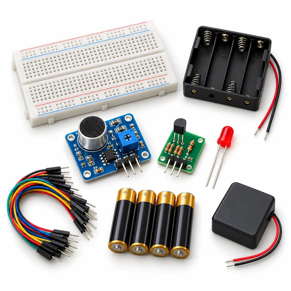 TechyTron
Sound Trigger Light Kit
₹609.00Earn 6 points TechyTron
Tilt Alarm Lab Kit
₹631.00Earn 6 points TechyTron
Touch Pad Light Kit
₹519.00Earn 5 points TechyTron
Transistor Light Switch Kit
₹521.50Earn 5 points TechyTron
Voltage Explorer Kit
₹1,098.50Earn 10 pointsShop Related by product name
Related by product name
8 catalogue products Batteries, Power Supplies & Accessories
CR1616 Battery - Micro Lithium Coin Cell 3V
₹15.50 Batteries, Power Supplies & Accessories
CR2025 Battery - Micro Lithium Coin Cell 3V
₹12.00EYE BLINK SENSOR
₹140.00Earn 1 points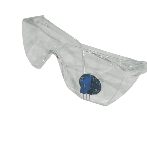 Biomedical Sensors
Eye Blink Sensor module for Arduino Raspberry Pi
₹153.50Earn 1 points Biomedical Sensors
Eye Blink Sensor with Goggles
₹144.00Earn 1 points Arduino
MEGA 2560 R3 Development Board - Compatible with Arduino
₹1,081.00Earn 10 points Discrete LEDs
RGB LED 5mm with 2 pin - Auto Flashing
₹3.50 Sensor Modules