
 TechyTron
Soil Moisture Signal Kit
SKU: TT-SE-05-09
₹608.00
Includes 18% GST
Earn 6 reward points per unit. How rewards work
Compare dry and damp soil using a sensor threshold. Classes 5-6 · Ages 10–12. Complete electronics kit with an illustrated guide.
Delivery options
Courier from ₹79.00 per order · Free above ₹999.00
Product description
Classes 5-6, typical ages 10–12. Age ranges vary by learner. Guided low-voltage electronics.
Activity engagement
45–65 minutes. Explore 5–10 min · Build 15–20 min · Test and discuss 25–35 min. Estimated time for building, testing and discussion.
What you need
No computer required. An adult helps inspect connections.
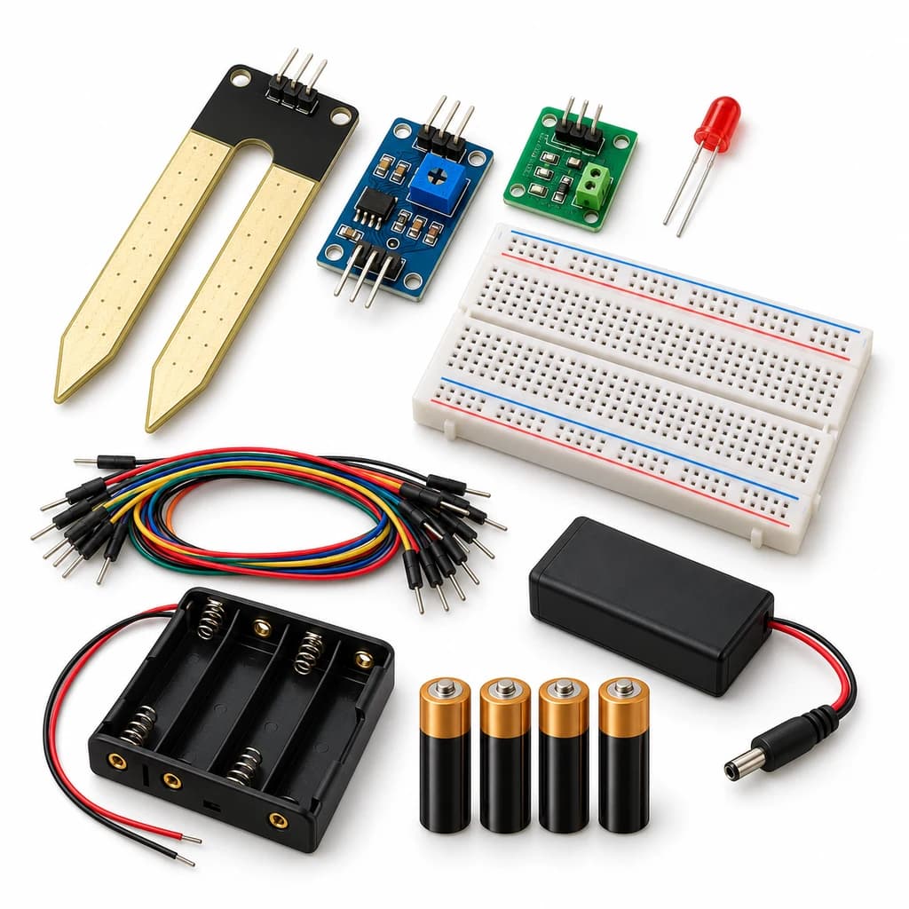
Included components
- Small Breadboard / Mini Solderless Board - 400 points — 1 breadboard
- Jumper Wire Combo - Male to Male, Male to Female and Female to Female Breadboard Connecting Wires (10 Qty Each) — 1 set
- Illustrated Activity Guide and Observation Sheets — 1 set
- Fitted Headers and Labelled Connection Leads — 1 set
- 4 CELL AA BATTERY HOLDER WITH SWITCH / COVER — 1 holder
- AA BATTERY — 4 battery (individual units)
- Regulated 5 V Power Supply with Short-Circuit Protection — 1 power supply
- Soil Moisture Sensor Module — 1 sensor set
- 5 V Sensor Output Driver with Trigger Selector — 1 interface circuit
- 5mm LED - Red Color — 1 LED
- 330 Ω 1/4 Watts (10 PCS) — 1 resistor
What you learn
- Dampness usually changes probe conductivity enough to alter the threshold output.
- A comparator turns a changing sensor signal into a digital threshold output.
- A separate output driver keeps the sensor signal separate from its load.
Connection guide
- soil moisture sensor VCC/GND → regulated +5 V/GND; its labelled DO output → driver IN.
- Driver VCC/GND → the same supply; use its supplied active-low/high trigger selector to match the module.
- Driver OUT → 330 Ohm → LED anode; LED cathode → GND.
Steps to make it
- Disconnect all power and identify the supplied part labels and pinouts before wiring.
- Switch the supply off and identify the sensor DO terminal; do not confuse it with AO.
- Connect the sensor, preassembled labelled driver and output using the connection card.
- Power on and adjust the sensor sensitivity at the baseline condition until the output is stable.
- Insert the probe to the same depth in dry and lightly damp soil samples, powering it only during readings.
- Repeat five controlled trials, changing only one condition, then switch off and dry/clean the sensing surface as appropriate.
Test challenge
Insert the probe to the same depth in dry and lightly damp soil samples, powering it only during readings.
Observation task
Sample label, insertion depth, threshold setting and LED state.
Expected result
Dampness usually changes probe conductivity enough to alter the threshold output. The driver makes that change visible or audible.
If it does not work
Check the DO pin, shared ground, sensitivity setting and driver trigger selector. A brief sensor pulse gives only a brief output; this is not a latching alarm.
Try next
Explain why salt content and soil type prevent treating this as an accurate water-percentage meter.
Use and supervision
Use only supplied 5 V DC. Keep the breadboard, power unit and driver dry; only the removable probe/plate contacts the sample. Disconnect power before handling wet parts. Clean and dry after use. Adult guidance is recommended.
How this experiment works
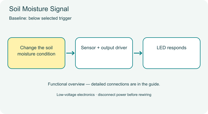
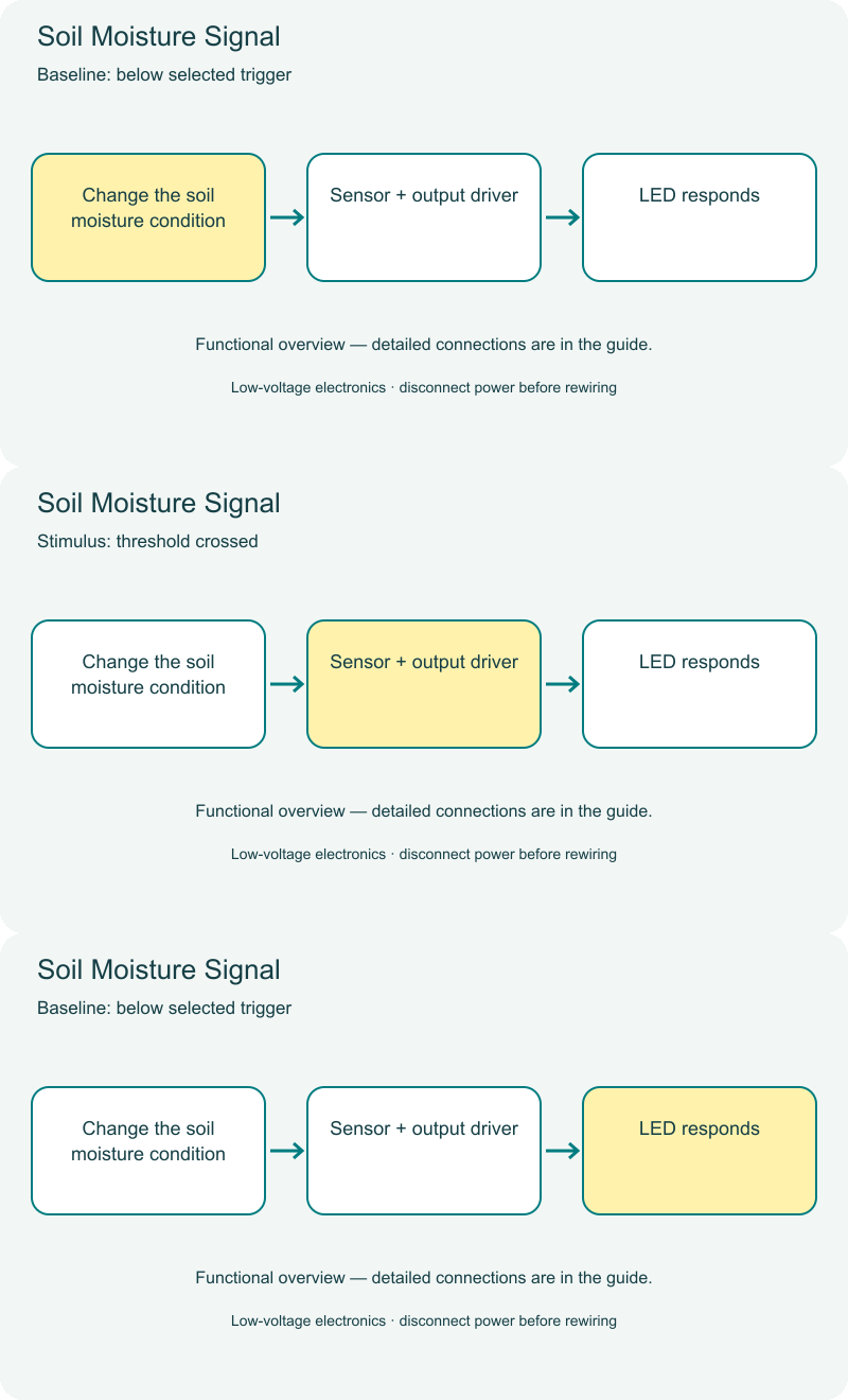
Cover illustrations show component types. Functional animations explain principles and are not recorded prototype tests. Follow the supplied connection labels and pinouts.
Customer feedback
Reviews
No published reviews yet. Be the first to share useful feedback.
Shop Related in this category
Related in this category
9 catalogue productsTechyTron TechyTron
Capacitor Countdown Kit
₹537.50Earn 5 points TechyTron
Heat Sense Alarm Kit
₹631.00Earn 6 points TechyTron
Rain Drop Alarm Kit
₹637.00Earn 6 points TechyTron
Sound Trigger Light Kit
₹609.00Earn 6 points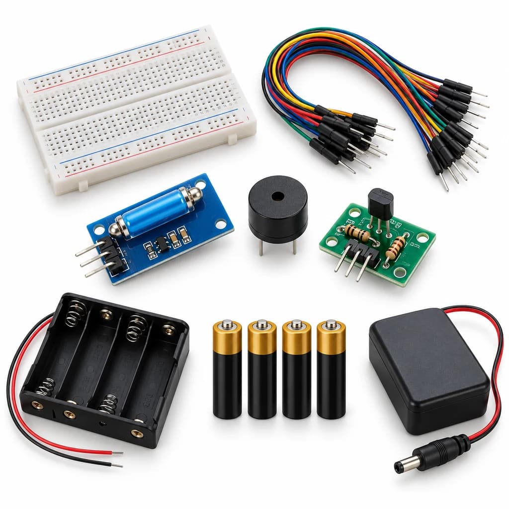 TechyTron
Tilt Alarm Lab Kit
₹631.00Earn 6 points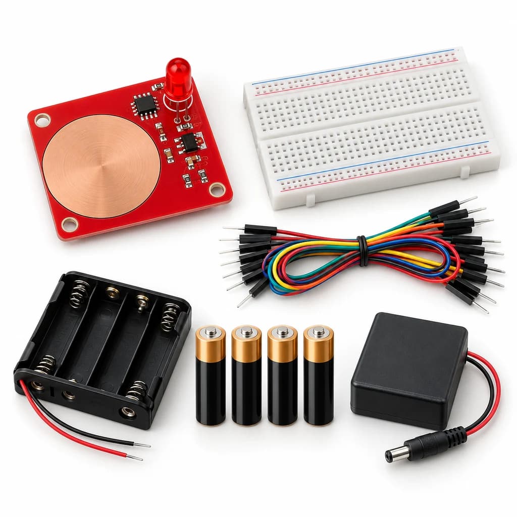 TechyTron
Touch Pad Light Kit
₹519.00Earn 5 points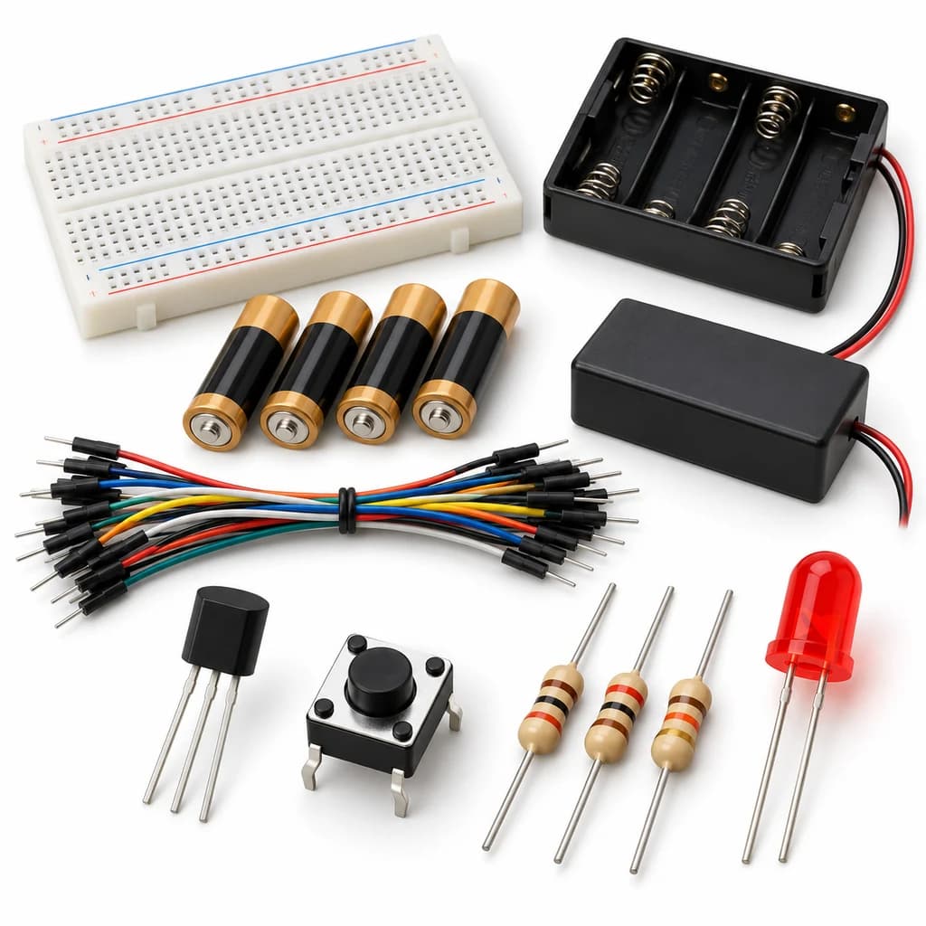 TechyTron
Transistor Light Switch Kit
₹521.50Earn 5 points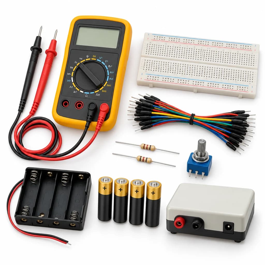 TechyTron
Voltage Explorer Kit
₹1,098.50Earn 10 pointsShop Related by product name
Related by product name
10 catalogue products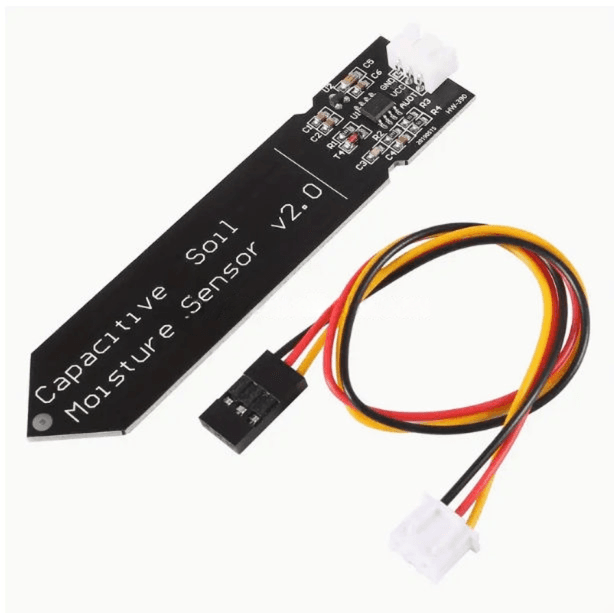 Agriculture & Water Sensors
Capacitive Soil Moisture Sensor V2.0 Module For Arduino/ Raspberry Pi
₹66.00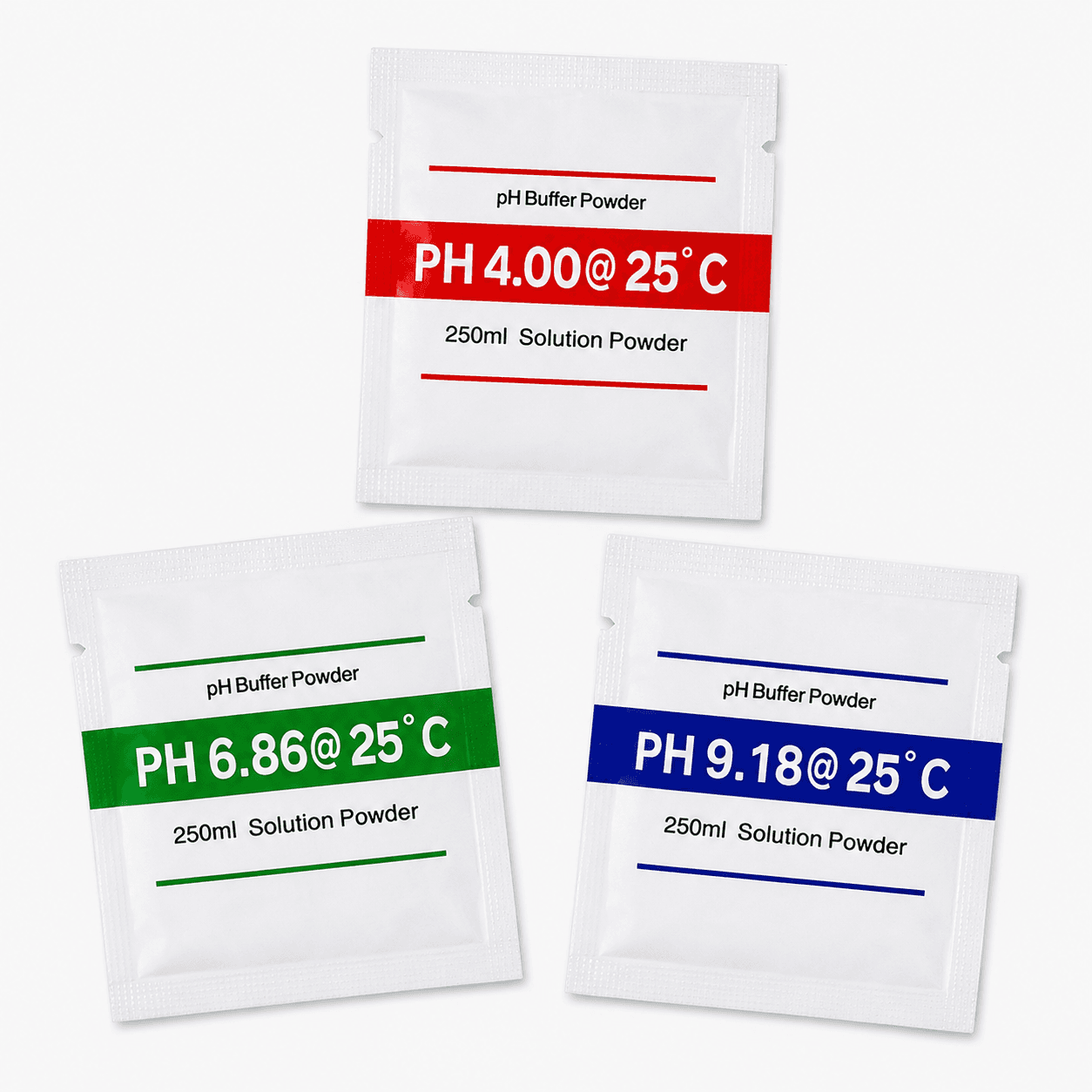 Miscellaneous
pH Buffer Powder Calibration Solution Kit – pH 4.00, 6.86 & 9.18 for pH Meter Calibration
₹99.00 Sensor Modules
5 in 1 Arduino Sensor Kit - Ultrasonic, PIR, IR Proximity, DHT11 and Soil Moisture Sensors
₹312.50Earn 3 pointsCAPACITIVE SOIL SENSOR
₹58.00 Agriculture & Water Sensors
Capacitive Soil Moisture Sensor V2.0
₹61.50 Digital Temperature Sensors
DS18B20 Temperature Sensor Original
₹40.00 Digital Temperature Sensors
DS18B20 Waterproof Temperature Sensor Probe
₹63.50 Agriculture & Water Sensors
Elecrow Crowtail Capacitive Moisture Sensor V2.0 for Arduino & IoT
₹186.50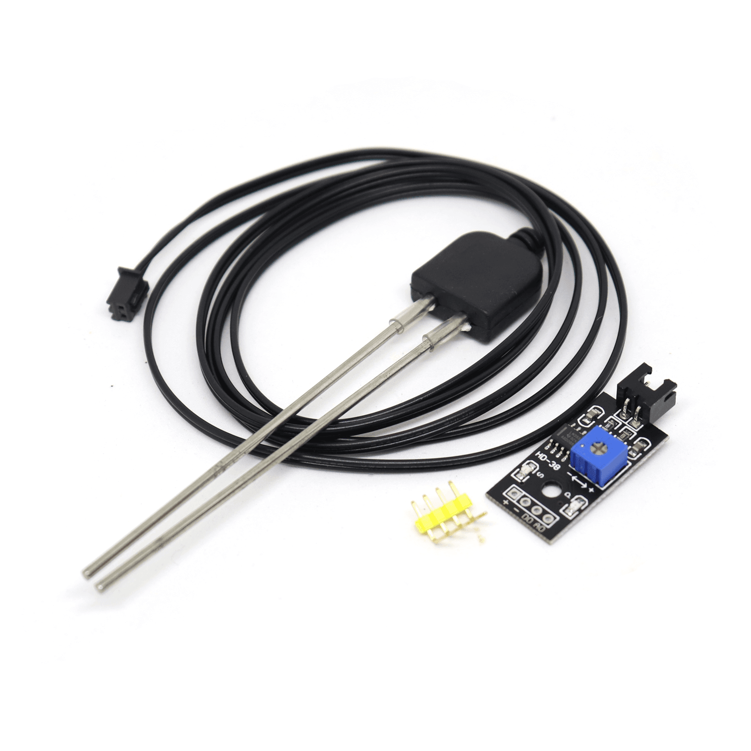 Agriculture & Water Sensors
High Quality Resistive Soil Moisture Module with Corrison Resistant Probe
₹277.50Earn 2 points Agriculture & Water Sensors