
 TechyTron
Power and Energy Monitor Kit
SKU: TT-SE-11-05
₹1,074.50
Includes 18% GST
Earn 10 reward points per unit. How rewards work
Measure low-voltage load current, power and accumulated energy. Classes 11-12 · Ages 16–18. Complete electronics kit with an illustrated guide.
Delivery options
Courier from ₹79.00 per order · Free above ₹999.00
Product description
Classes 11-12, typical ages 16–18. Age ranges vary by learner. Guided low-voltage electronics.
Activity engagement
105–150 minutes. Explore 20–30 min · Build 35–50 min · Test and discuss 50–70 min. Estimated time for building, testing and discussion.
What you need
A computer with a USB port and Arduino IDE is required and is not included. Wi-Fi/BLE experiments also require the local network or phone specified in the guide.
Included components
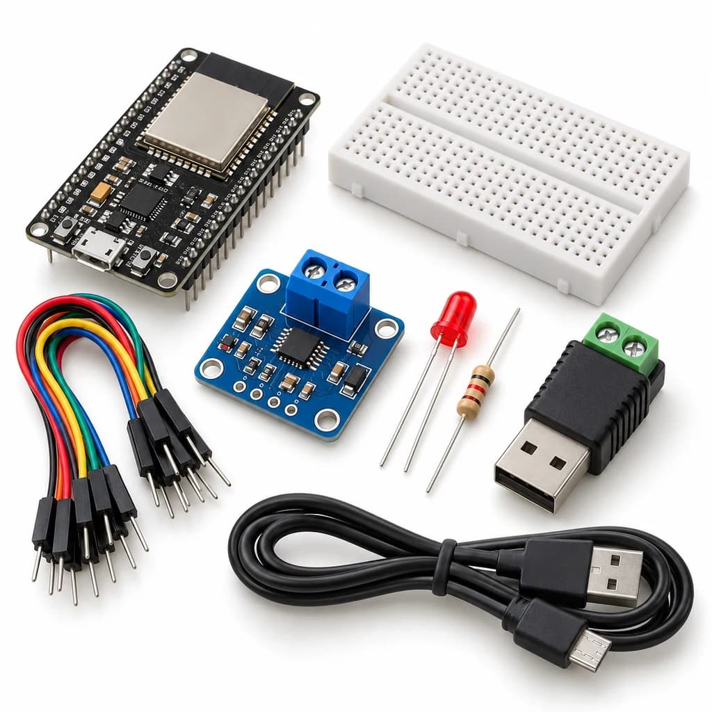
- Small Breadboard / Mini Solderless Board - 400 points — 1 breadboard
- Jumper Wire Combo - Male to Male, Male to Female and Female to Female Breadboard Connecting Wires (10 Qty Each) — 1 set
- Illustrated Activity Guide and Observation Sheets — 1 set
- Fitted Headers and Labelled Connection Leads — 1 set
- ESP32S 38Pin Development Board (WIFI+BLUETOOTH) — 1 controller board
- MICRO USB DATA CABLE — 1 data cable
- CJMCU-219 INA219 I2C Interface No Drift Bi-directional Current / Power Monitoring Sensor Module — 1 sensor module
- 5mm LED - Red Color — 1 LED
- 330 Ω 1/4 Watts (10 PCS) — 1 resistor
- 5 V USB Power Lead with Screw-Terminal Output — 1 lead
- 5V 2A Adapter (Without Cable) - 10W Adapter for Raspberry Pi 3 — 1 power supply
What you learn
- Current sensing is inserted in series with a load.
- Power and energy use different units.
- Energy is estimated by integrating power over elapsed time.
Connection guide
- INA219 VCC → 3.3 V, GND → ESP32 GND, SDA → GPIO21, SCL → GPIO22.
- Supplied separate 5 V load supply positive → INA219 VIN+; VIN− → 330 Ohm → LED anode; LED cathode → load supply GND.
- Load-supply GND → ESP32 GND. Keep its +5 V separate from USB-powered board +5 V.
Steps to make it
- Disconnect all power and identify the supplied part labels and pinouts before wiring.
- Wire the current path in series and check it with power disconnected.
- Install libraries, upload and enable the separate 5 V load supply.
- Observe volts, milliamps, milliwatts and accumulated milliwatt-hours for two minutes.
- Disconnect only the load branch with power off, restart and compare the near-zero-load reading.
- Change only the named parameter for the extension, repeat the controlled trials, save observations and disconnect power afterward.
Programming resources
Arduino IDE: install esp32 by Espressif Systems 3.x; select ESP32 Dev Module for the supplied classic WROOM board. Serial Monitor: 115200 baud. GPIO is 3.3 V only.
Libraries to install
- Adafruit INA219
- Adafruit BusIO
Test challenge
Compare integrated energy with average measured power multiplied by the test duration in hours.
Observation task
Elapsed seconds, load voltage, current mA, power mW and energy mWh.
Expected result
Energy accumulates while a valid non-negative load power is measured and resets on board restart.
If it does not work
Check VIN+/VIN− orientation and common grounds. Do not wire the current path across a supply as a short.
Try next
Estimate uncertainty from current-sensor offset and sampling interval; this is not a billing meter.
Use and supervision
Use only the supplied low-voltage DC parts. Disconnect power before rewiring; check polarity and labelled pinouts. No soldering or exposed mains connections. Adult guidance is recommended.
How this experiment works
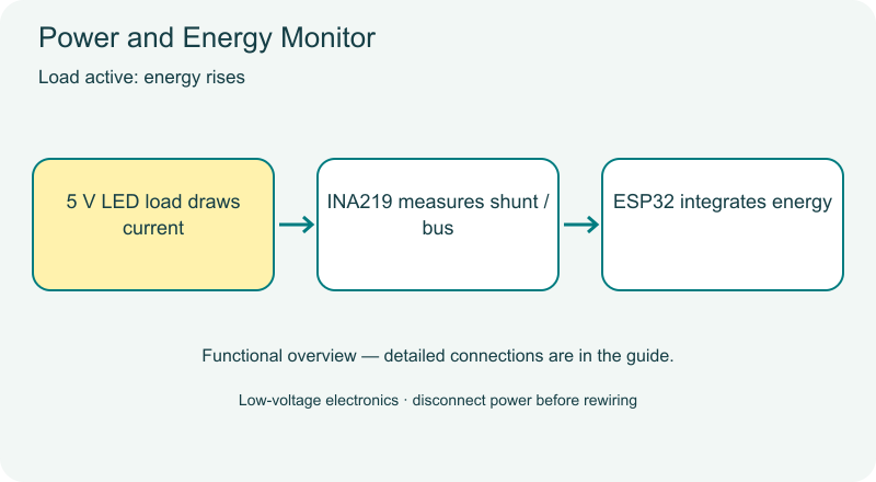
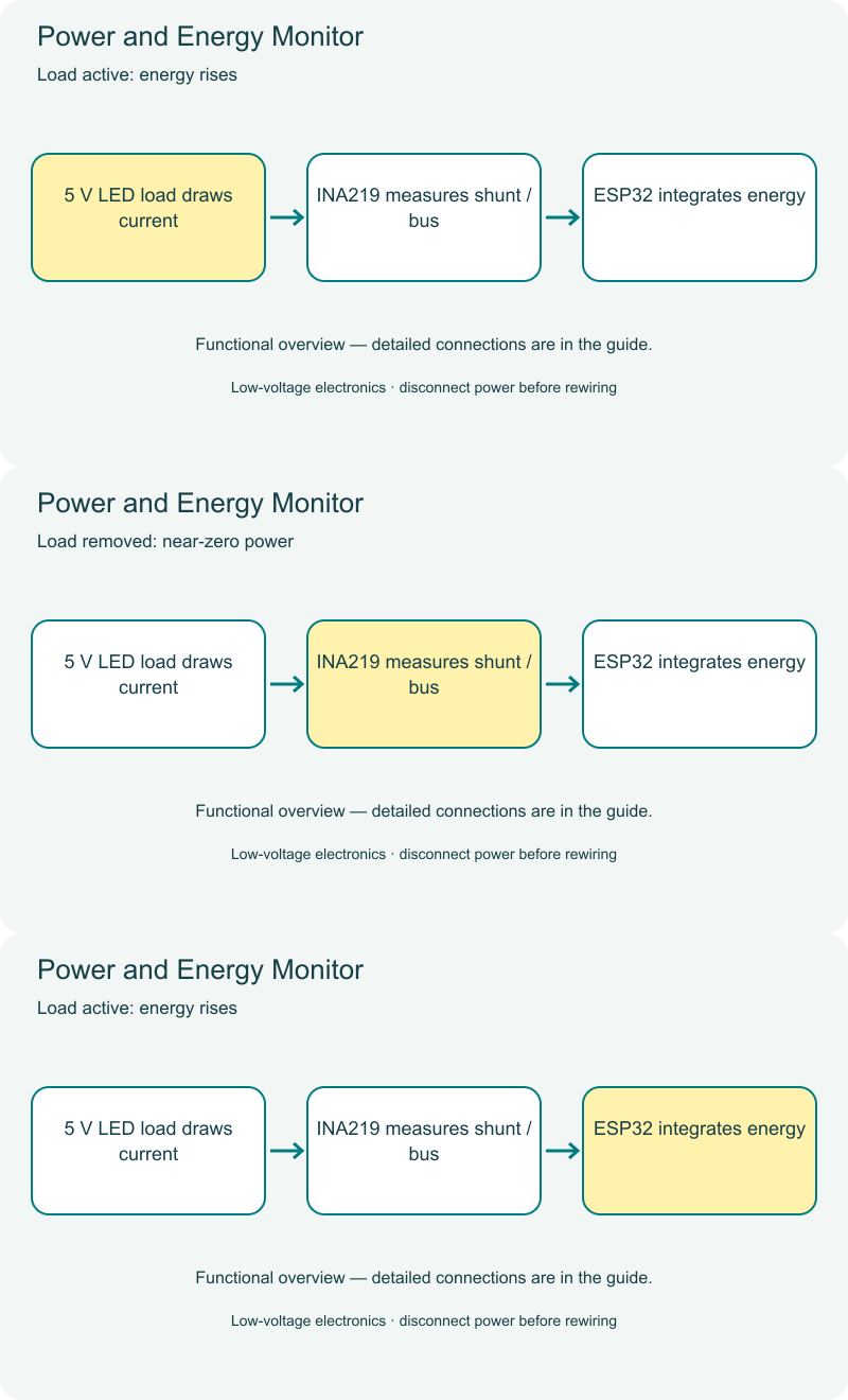
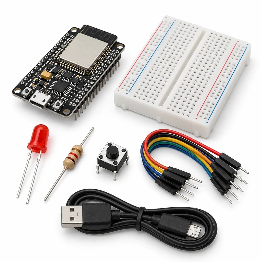
Cover illustrations show component types. Functional animations explain principles and are not recorded prototype tests. Follow the supplied connection labels and pinouts.
Customer feedback
Reviews
No published reviews yet. Be the first to share useful feedback.
Shop Related in this category
Related in this category
9 catalogue productsTechyTron TechyTron
IoT Tank Level Monitor Kit
₹833.00Earn 8 points TechyTron
Local Wi-Fi Sensor Dashboard Kit
₹832.50Earn 8 points TechyTron
MQTT Environment Station Kit
₹1,055.50Earn 10 points TechyTron
PID Light Control Lab Kit
₹755.50Earn 7 points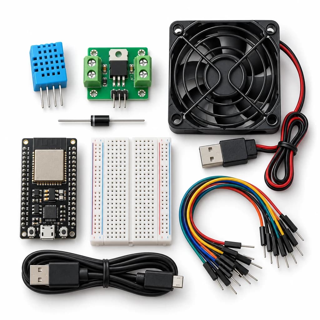 TechyTron
Room Comfort Controller Kit
₹1,253.00Earn 12 points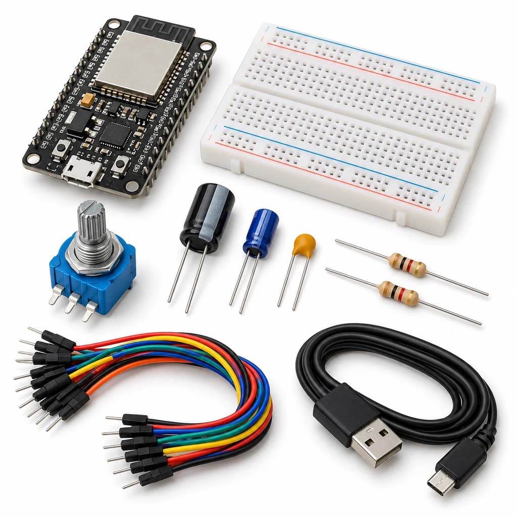 TechyTron
Signal Sampling and Filtering Kit
₹738.00Earn 7 points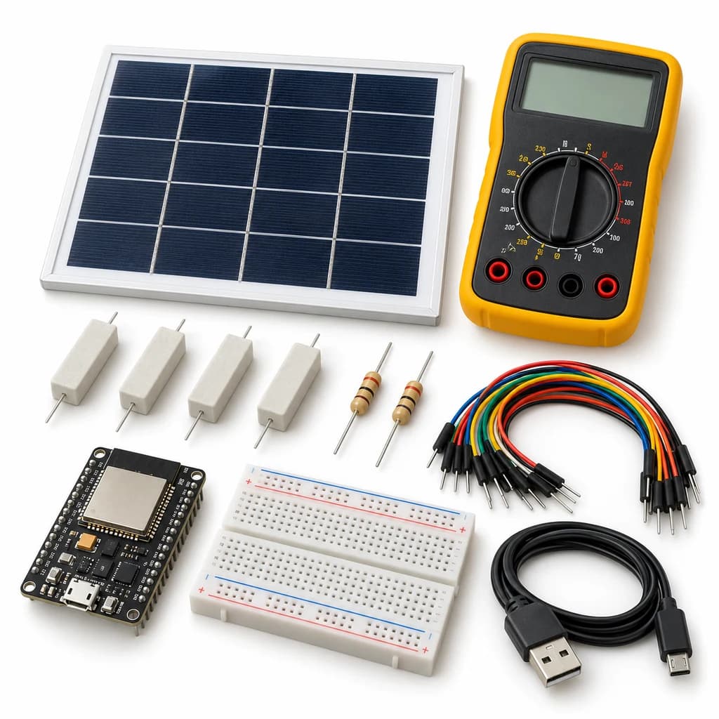 TechyTron
Solar I-V Explorer Kit
₹1,344.50Earn 13 points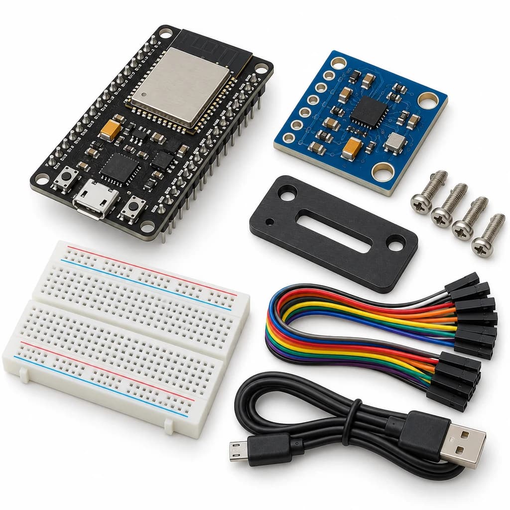 TechyTron
Vibration Spectrum Lab Kit
₹947.50Earn 9 pointsShop Related by product name
Related by product name
10 catalogue products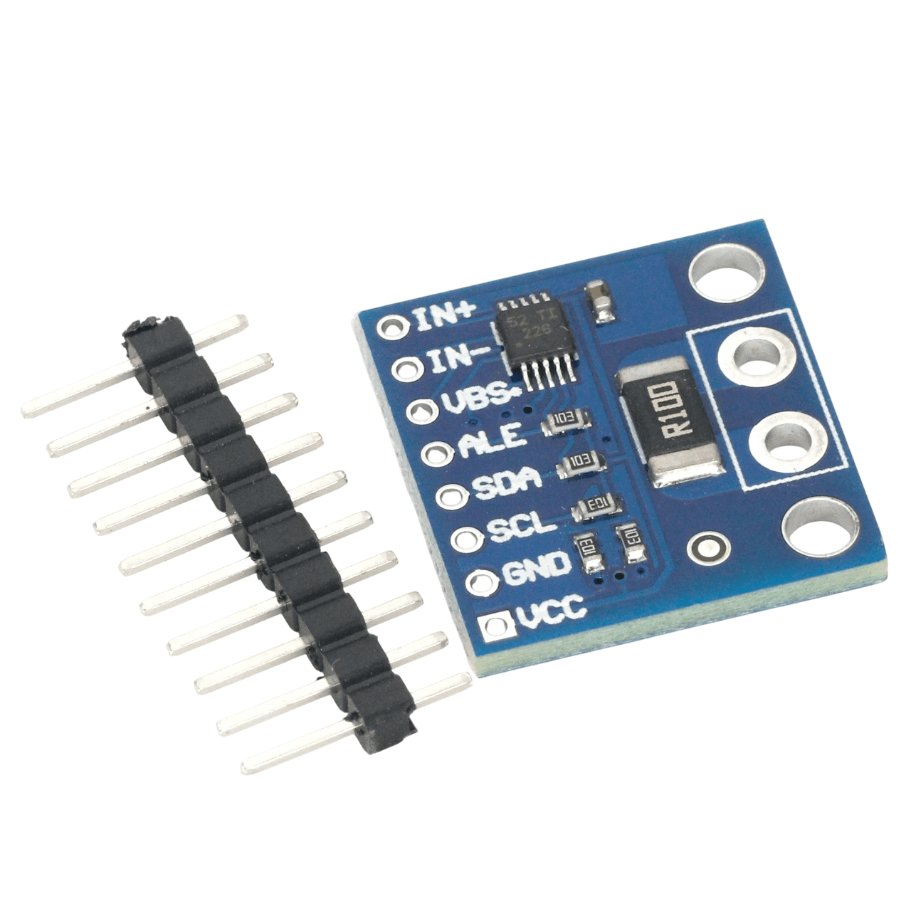 Sensor Modules
INA226 – I2C Bi-Directional Voltage Current Power Alert Monitor Module
₹122.50Earn 1 points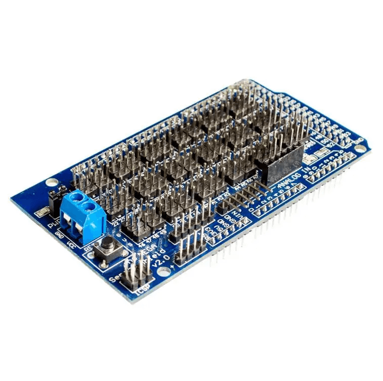 Board Support
Sensor Shield V2.0 for Arduino Mega 2560 R3
₹200.50Earn 2 points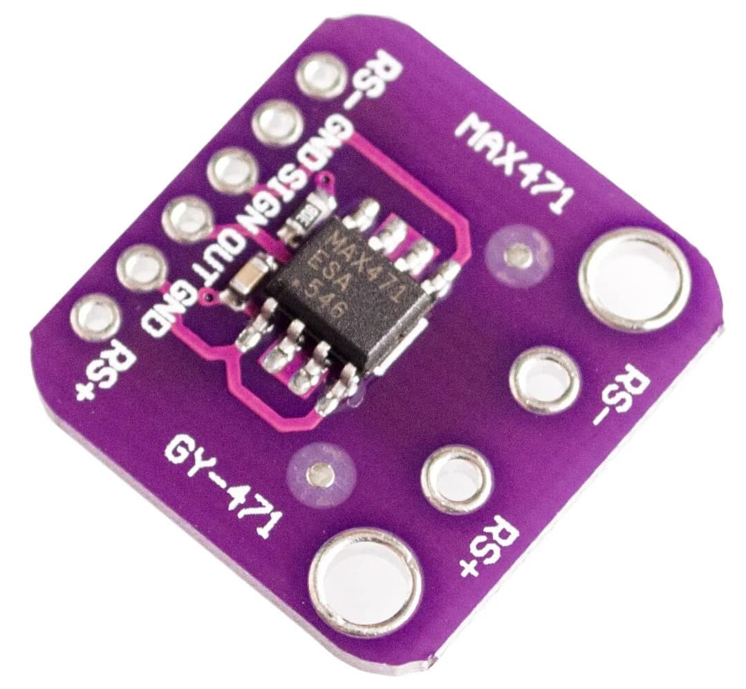 Current Sensors
GY-471 3A Range MAX471 Current Sensor Module
₹265.50Earn 2 points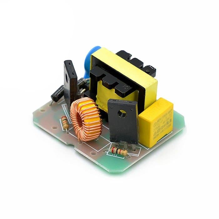 Voltage Regulators & DC-DC Converters
12V DC to 220V AC 40W Step-Up Inverter Booster Module
₹194.50Earn 1 points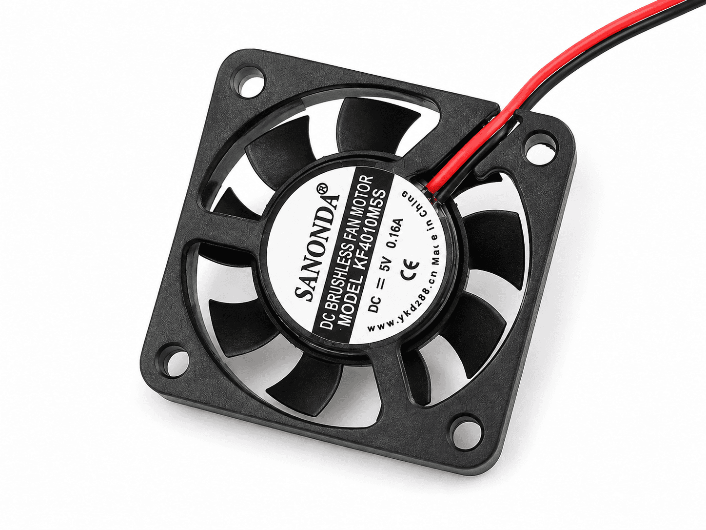 Other Motors, Drivers & Pumps
5V DC Cooling Fan – 40×40mm, 0.16A, 2-Wire
₹119.00Earn 1 points Electronic Modules
Auto-Power-On Module for Desktop PCs and Servers
₹250.00Earn 2 points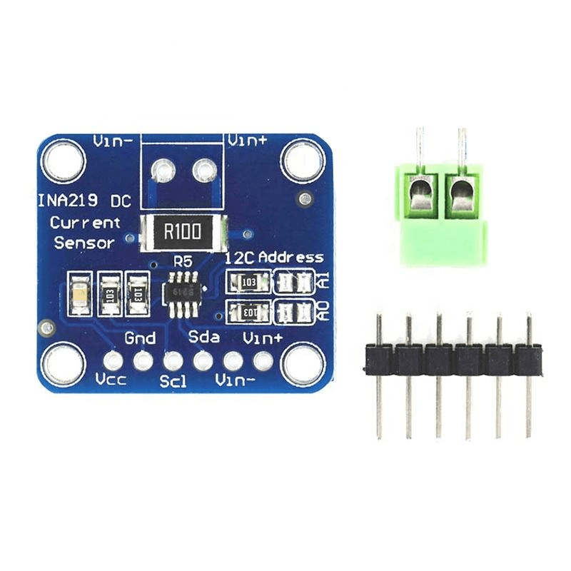 Current, Voltage & Energy Sensors
CJMCU-219 INA219 I2C Interface Zero Drift Bi-directional Current / Power Supply Monitoring Module
₹99.00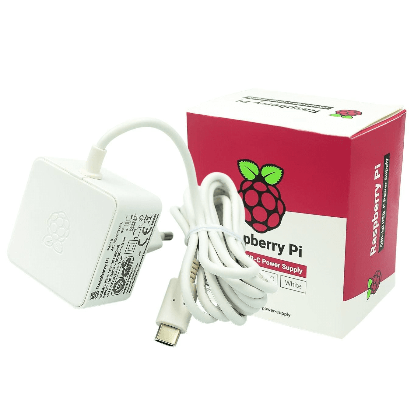 Other Raspberry Pi
Raspberry Pi 4 Official 15W USB C Power Supply
₹737.50Earn 7 points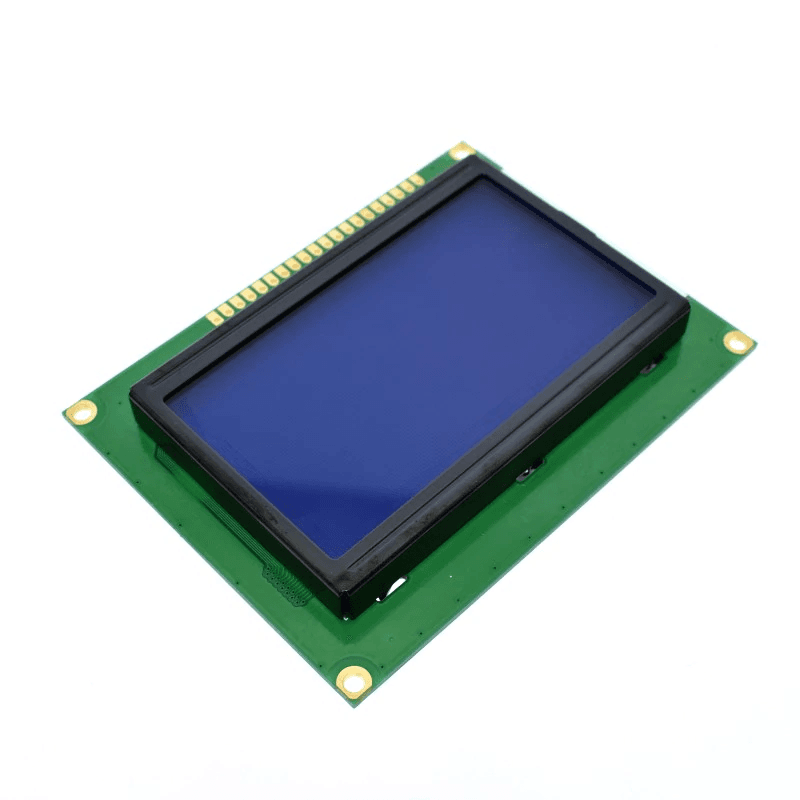 Graphic LCD (GLCD)
12864 128 x 64 Graphic LCD Display Module With Blue Backlight For Arduino
₹707.00Earn 7 points Graphic LCD (GLCD)