
 TechyTron
Solar I-V Explorer Kit
SKU: TT-SE-11-04
₹1,344.50
Includes 18% GST
Earn 13 reward points per unit. How rewards work
Measure a small solar panel under different electrical loads. Classes 11-12 · Ages 16–18. Complete electronics kit with an illustrated guide.
Delivery options
Courier from ₹79.00 per order · Free above ₹999.00
Product description
Classes 11-12, typical ages 16–18. Age ranges vary by learner. Guided low-voltage electronics.
Activity engagement
120–180 minutes. Explore 20–35 min · Build 40–60 min · Test and discuss 60–85 min. Estimated time for building, testing and discussion.
What you need
A computer with a USB port and Arduino IDE is required and is not included. Wi-Fi/BLE experiments also require the local network or phone specified in the guide.
Included components
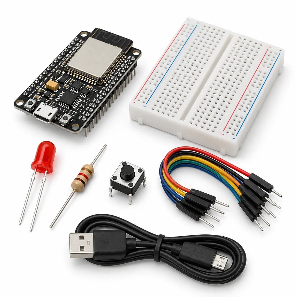
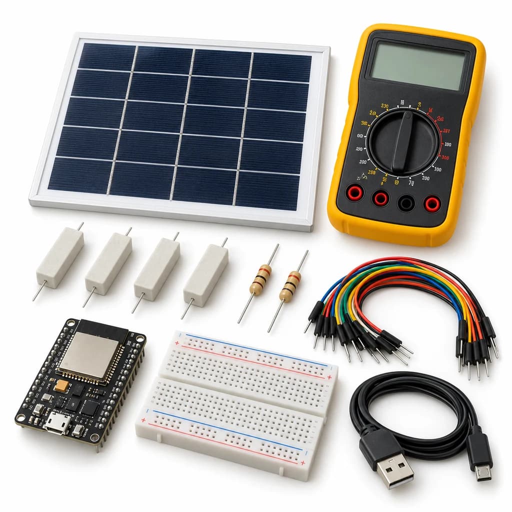
- Small Breadboard / Mini Solderless Board - 400 points — 1 breadboard
- Jumper Wire Combo - Male to Male, Male to Female and Female to Female Breadboard Connecting Wires (10 Qty Each) — 1 set
- Illustrated Activity Guide and Observation Sheets — 1 set
- Fitted Headers and Labelled Connection Leads — 1 set
- ESP32S 38Pin Development Board (WIFI+BLUETOOTH) — 1 controller board
- MICRO USB DATA CABLE — 1 data cable
- 6V - 100 mA (70 mmx70 mm) Solar panel — 1 solar panel
- DT9205A Digital Multimeter with Probes and Battery — 1 multimeter
- 100 Ohm 1 W Through-Hole Power Resistor — 1 resistor
- 220 Ohm 1 W Through-Hole Power Resistor — 1 resistor
- 470 Ohm 1 W Through-Hole Power Resistor — 1 resistor
- 1000 Ohm 1 W Through-Hole Power Resistor — 1 resistor
- 10K Ω 1/4 Watts (10 PCS) — 4 resistor (individual units)
What you learn
- Panel voltage changes with illumination and load.
- For a known resistive load, current is approximately V/R.
- Maximum measured power is a property of the tested conditions and available load points.
Connection guide
- Panel positive → two 10 kOhm resistors in series → GPIO34 node → one 10 kOhm → panel negative. Panel negative → ESP32 GND. A fourth 10 kOhm is a supplied spare.
- Use the 100, 220, 470 and 1000 Ohm 1 W resistors one at a time directly across the panel; the divider remains in parallel.
- Meter in DC volts mode across the panel; COM and V sockets only. Do not use current mode across the panel.
Steps to make it
- Disconnect all power and identify the supplied part labels and pinouts before wiring.
- Verify the 3:1 divider before connecting the solar panel and confirm its open-circuit voltage is no higher than 9 V.
- Power ESP32 by USB and compare ADC-derived panel voltage against the meter; adjust dividerFactor if required.
- Under fixed illumination, disconnect the panel before changing each load; enter its measured resistance in the local sketch.
- Record load voltage and calculate load current/power; then repeat one load with partial shading.
- Change only the named parameter for the extension, repeat the controlled trials, save observations and disconnect power afterward.
Programming resources
Arduino IDE: install esp32 by Espressif Systems 3.x; select ESP32 Dev Module for the supplied classic WROOM board. Serial Monitor: 115200 baud. GPIO is 3.3 V only.
Uses the selected board core libraries.
Test challenge
Compare at least four load points under the same light, then repeat the highest measured power point in shade.
Observation task
Illumination condition, load resistance, meter voltage, ADC voltage, calculated load current and power.
Expected result
Each resistor gives an approximate operating point. I=V/R refers to the selected load branch; divider current is a small additional branch.
If it does not work
Check divider orientation and stop if panel open-circuit voltage exceeds 9 V. The 1 W load resistors are required; do not substitute tiny 1/4 W parts.
Try next
Plot I against V and P against V; explain why four points do not locate the exact maximum-power point.
Use and supervision
Use only the supplied 6 V/100 mA panel, no batteries or charging circuits. Keep panel open-circuit voltage at or below 9 V for this divider. Switch off/disconnect before changing loads; 1 W resistors may become warm.
How this experiment works
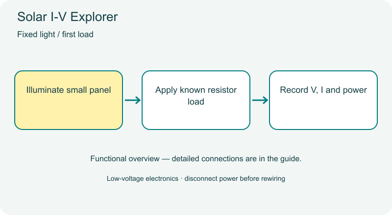
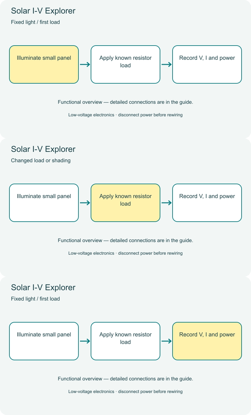
Cover illustrations show component types. Functional animations explain principles and are not recorded prototype tests. Follow the supplied connection labels and pinouts.
Customer feedback
Reviews
No published reviews yet. Be the first to share useful feedback.
Shop Related in this category
Related in this category
9 catalogue productsTechyTron TechyTron
IoT Tank Level Monitor Kit
₹833.00Earn 8 points TechyTron
Local Wi-Fi Sensor Dashboard Kit
₹832.50Earn 8 points TechyTron
MQTT Environment Station Kit
₹1,055.50Earn 10 points TechyTron
PID Light Control Lab Kit
₹755.50Earn 7 points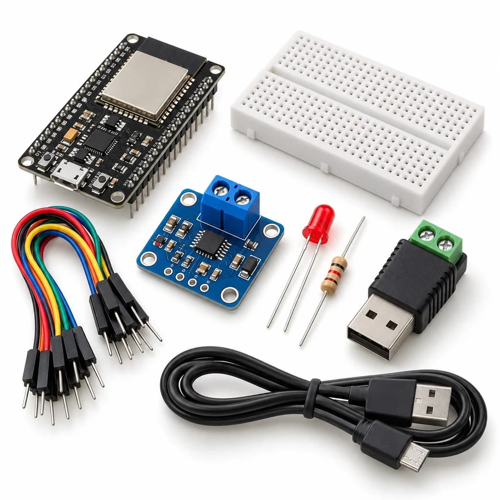 TechyTron
Power and Energy Monitor Kit
₹1,074.50Earn 10 points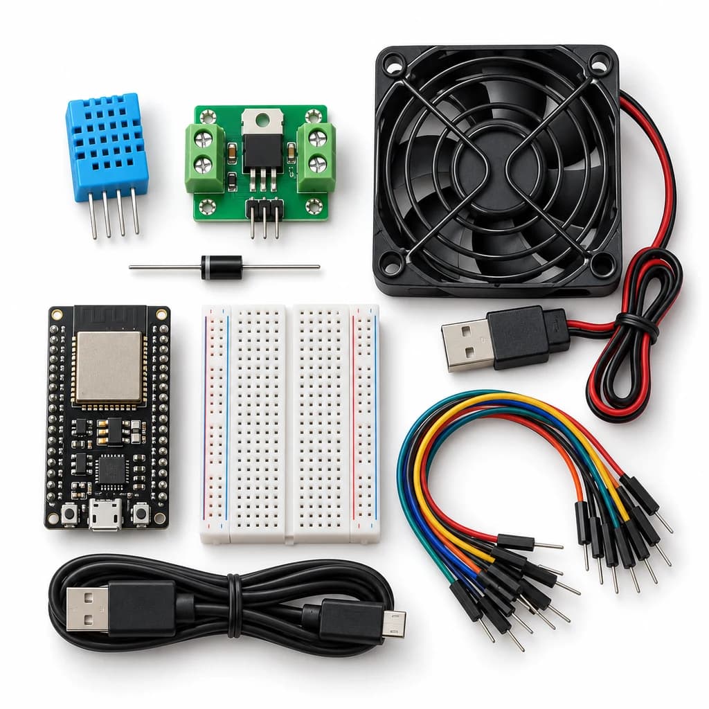 TechyTron
Room Comfort Controller Kit
₹1,253.00Earn 12 points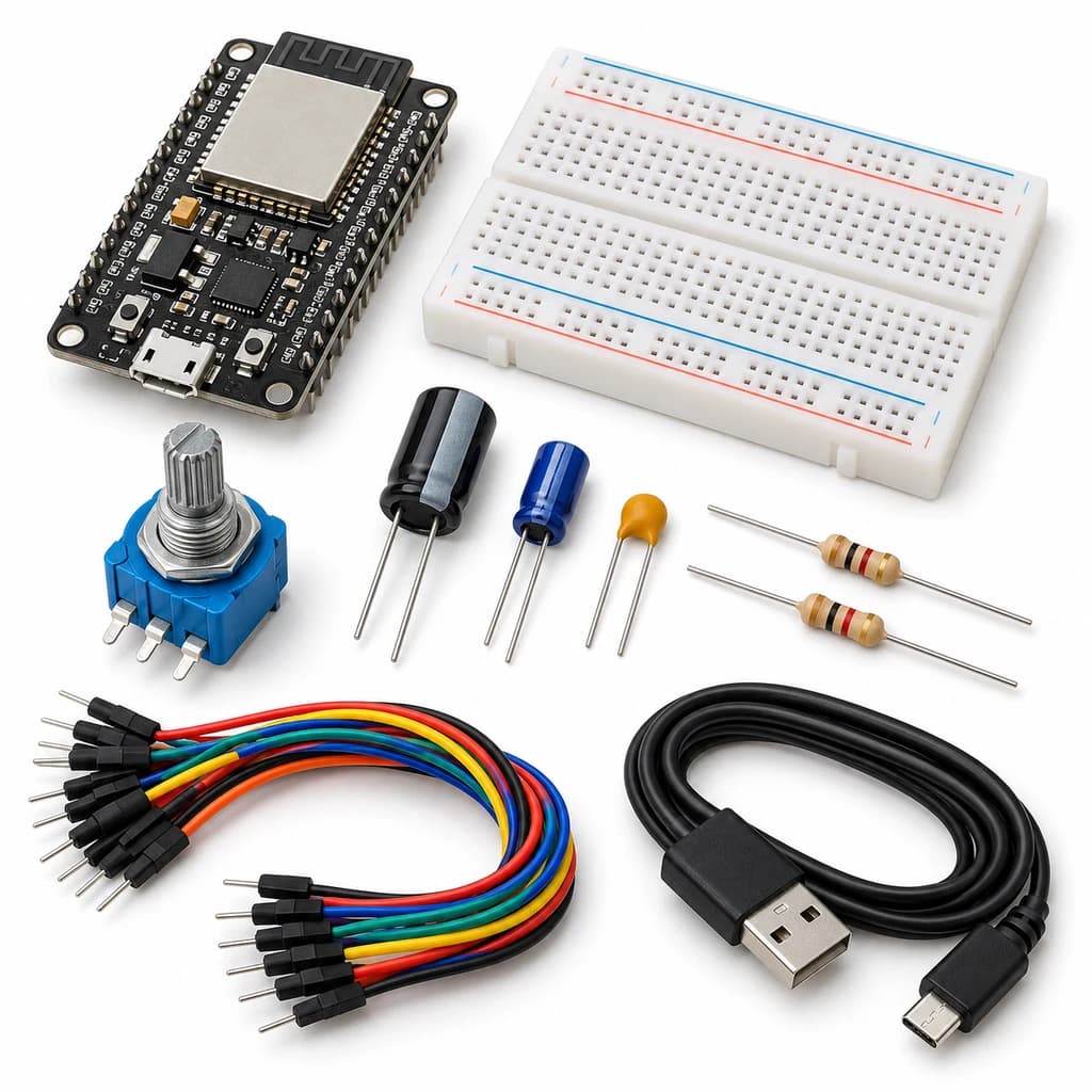 TechyTron
Signal Sampling and Filtering Kit
₹738.00Earn 7 points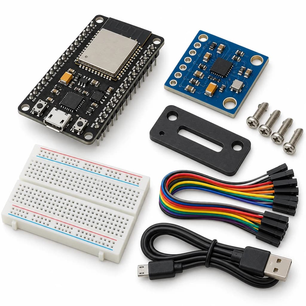 TechyTron
Vibration Spectrum Lab Kit
₹947.50Earn 9 pointsShop Related by product name
Related by product name
10 catalogue products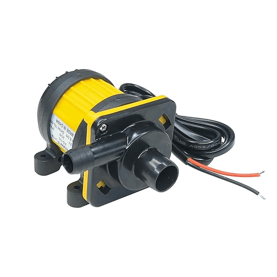 Pumps
12V 15-watt DC Submersible Under Water Pump
₹366.00Earn 3 points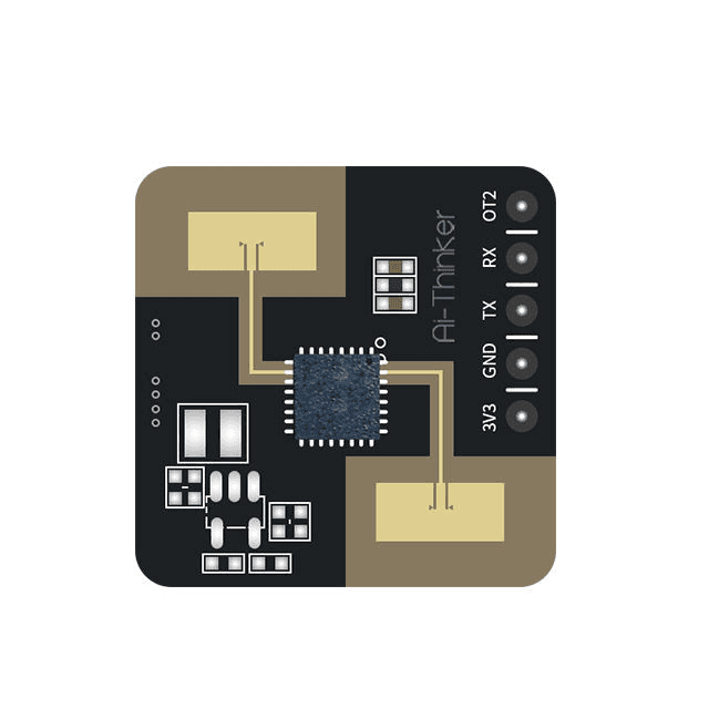 Radar & Motion Sensors
Ai-Thinker Rd-03L_V2 Low-Power 24GHz Human Presence Radar Sensor
₹531.00Earn 5 points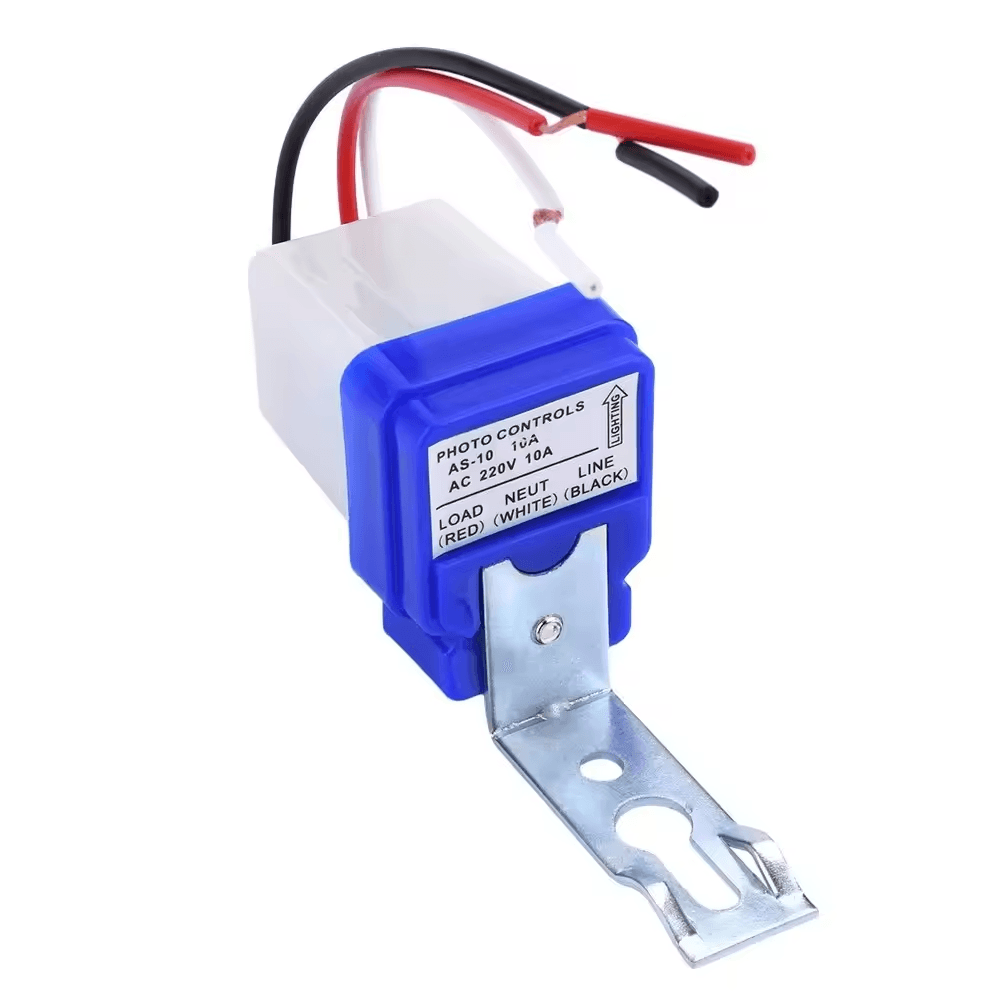 Environmental Sensors
Automatic On/Off Photocell Street Lamp Light Switch Controller AC 220V 50-60Hz 10A
₹141.50Earn 1 points Brushless DC Motors
Mini 12V DC 15W Brushless Submersible Solar Water Pump Motor
₹290.50Earn 2 points Brushless DC Motors
Mini 24V DC 12W Brushless Submersible Solar Water Pump Motor
₹455.50Earn 4 points Solar Modules
Mini Solar Charger Board for LiPo Battery with CN3065
₹100.50Earn 1 points Panel Meters
0.36 Inch 0-100V Three Wire DC Voltmeter
₹60.00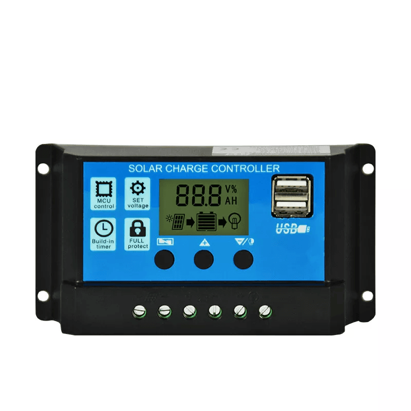 Solar Panels
10A Intelligent Solar Charge Controller With Timer and USB Mobile Charger Socket
₹472.00Earn 4 points Solar Modules
10A Smart Solar Charge Controller with Timer and USB Mobile Charger Socket
₹392.00Earn 3 points Batteries, Power Supplies & Accessories