
 TechyTron
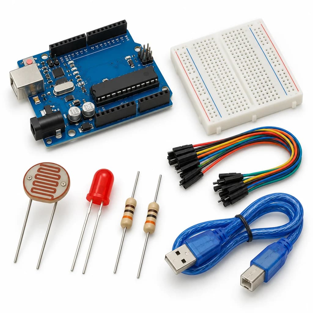
Smart Streetlight Control Kit
SKU: TT-SE-09-08
₹441.50
Includes 18% GST
Earn 4 reward points per unit. How rewards work
Program an automatic light with hysteresis and PWM dimming. Classes 9-10 · Ages 14–16. Complete electronics kit with an illustrated guide.
Delivery options
Courier from ₹79.00 per order · Free above ₹999.00
Product description
Classes 9-10, typical ages 14–16. Age ranges vary by learner. Guided low-voltage electronics.
Activity engagement
60–90 minutes. Explore 10–15 min · Build 20–30 min · Test and discuss 30–45 min. Estimated time for building, testing and discussion.
What you need
A computer with a USB port and Arduino IDE is required and is not included.
Included components
- Small Breadboard / Mini Solderless Board - 400 points — 1 breadboard
- Jumper Wire Combo - Male to Male, Male to Female and Female to Female Breadboard Connecting Wires (10 Qty Each) — 1 set
- Illustrated Activity Guide and Observation Sheets — 1 set
- Fitted Headers and Labelled Connection Leads — 1 set
- Arduino Uno R3 CH340G version compatible Arduino Development Board — 1 controller board
- USB A to B Programming Cable for Arduino Uno/ Arduino Mega — 1 data cable
- LDR Sensor (Light Dependent Resistor) - 5mm — 1 photoresistor
- 10K Ω 1/4 Watts (10 PCS) — 1 resistor
- 5mm LED - Red Color — 1 LED
- 330 Ω 1/4 Watts (10 PCS) — 1 resistor
What you learn
- Two switching thresholds can prevent chatter.
- PWM provides gradual brightness changes.
- A sensor should be shielded from its own controlled light when appropriate.
Connection guide
- 5 V → LDR → A0 node → 10 kOhm → GND.
- D9 → 330 Ohm → LED anode; cathode → GND. Keep the LED from shining directly on the LDR.
Steps to make it
- Disconnect all power and identify the supplied part labels and pinouts before wiring.
- Build the divider and LED output; upload and observe raw light values.
- Select darkOn and brightOff values between your covered and uncovered readings, keeping darkOn lower.
- Move slowly across the boundary and observe whether the output chatters.
- Compare this two-threshold behaviour with a single threshold and record the difference.
- Change only the named parameter for the extension, repeat the controlled trials, save observations and disconnect power afterward.
Programming resources
Arduino IDE: select Arduino Uno and the USB port. Use the supplied USB data cable. Serial Monitor/Plotter: 115200 baud.
Uses the selected board core libraries.
Test challenge
Hover light level near the boundary and count unwanted toggles over 30 seconds.
Observation task
Raw light, selected thresholds, LED state and toggle count.
Expected result
The LED turns on below the dark threshold and stays on until light exceeds the higher threshold; PWM changes brightness gradually.
If it does not work
Recalibrate thresholds for the room and check divider orientation; do not use this low-power LED model to switch mains lighting.
Try next
Add time-based dimming while keeping the hysteresis decision separate.
Use and supervision
Use only the supplied low-voltage DC parts. Disconnect power before rewiring; check polarity and labelled pinouts. No soldering or exposed mains connections. Adult guidance is recommended.
How this experiment works
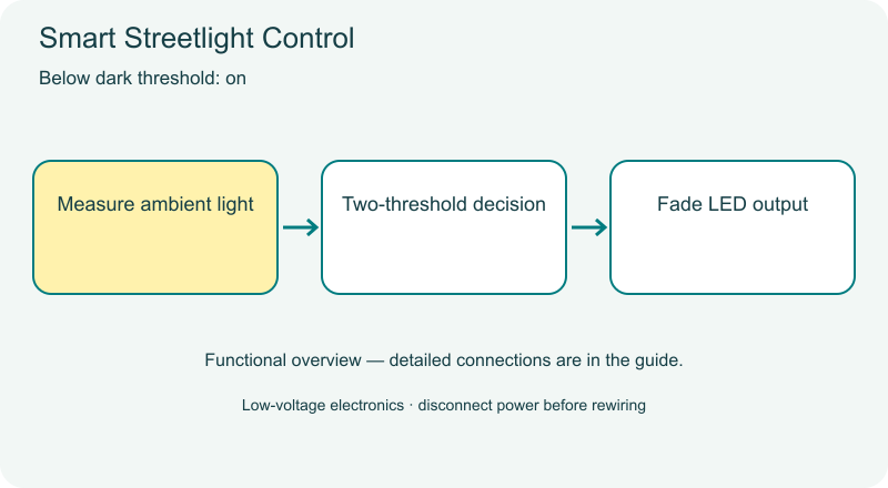
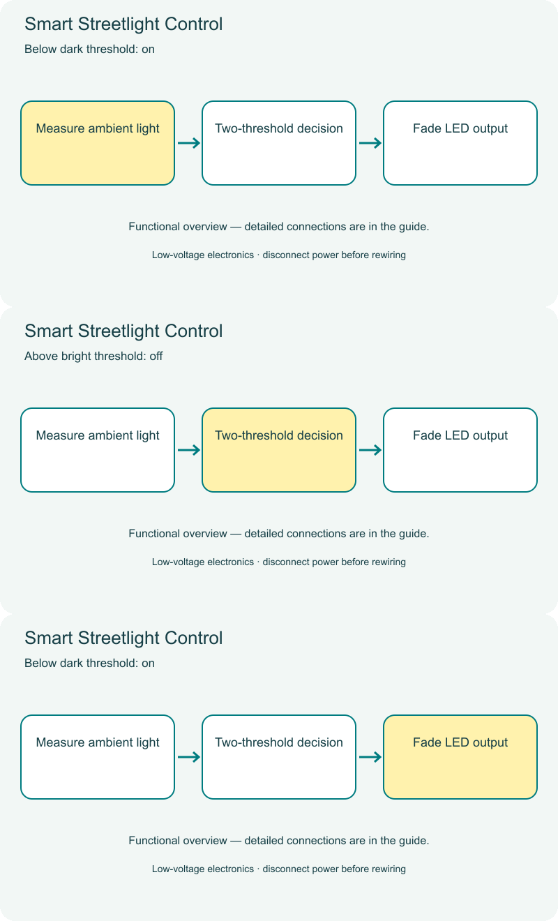
Cover illustrations show component types. Functional animations explain principles and are not recorded prototype tests. Follow the supplied connection labels and pinouts.
Customer feedback
Reviews
No published reviews yet. Be the first to share useful feedback.
Shop Related in this category
Related in this category
9 catalogue productsTechyTron TechyTron
Motion Event Alarm Kit
₹521.00Earn 5 points TechyTron
OLED Weather Dashboard Kit
₹833.50Earn 8 points TechyTron
Optical Speed Lab Kit
₹523.50Earn 5 points TechyTron
Precision Voltage Monitor Kit
₹1,137.50Earn 11 points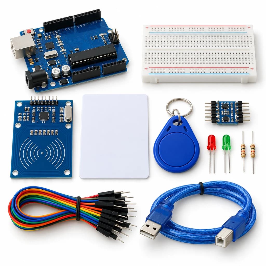 TechyTron
RFID Access Indicator Kit
₹593.50Earn 5 points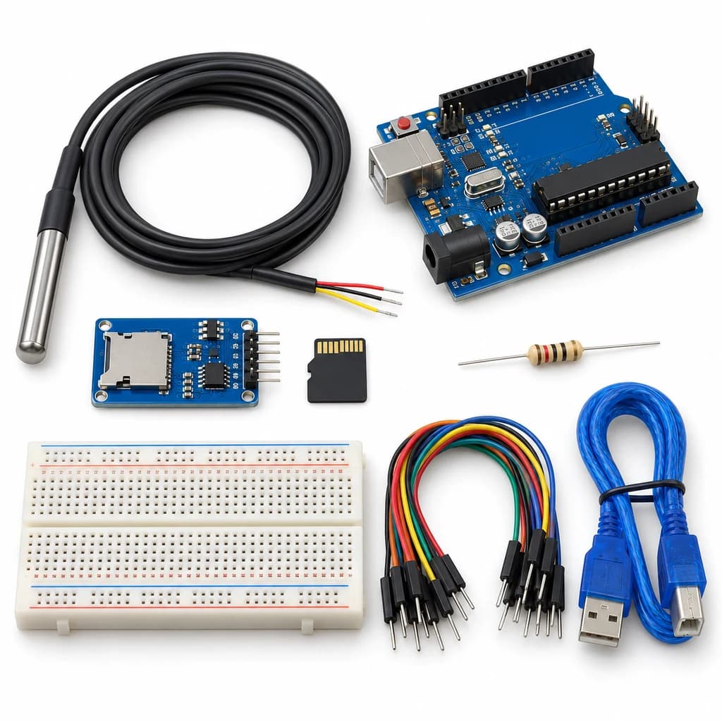 TechyTron
Temperature Data Recorder Kit
₹1,001.50Earn 10 points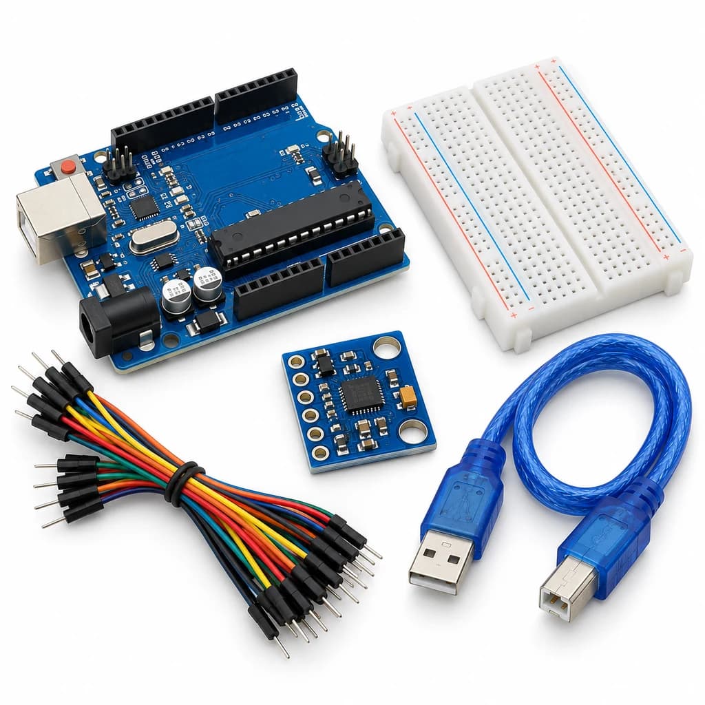 TechyTron
Tilt and Acceleration Logger Kit
₹702.00Earn 7 points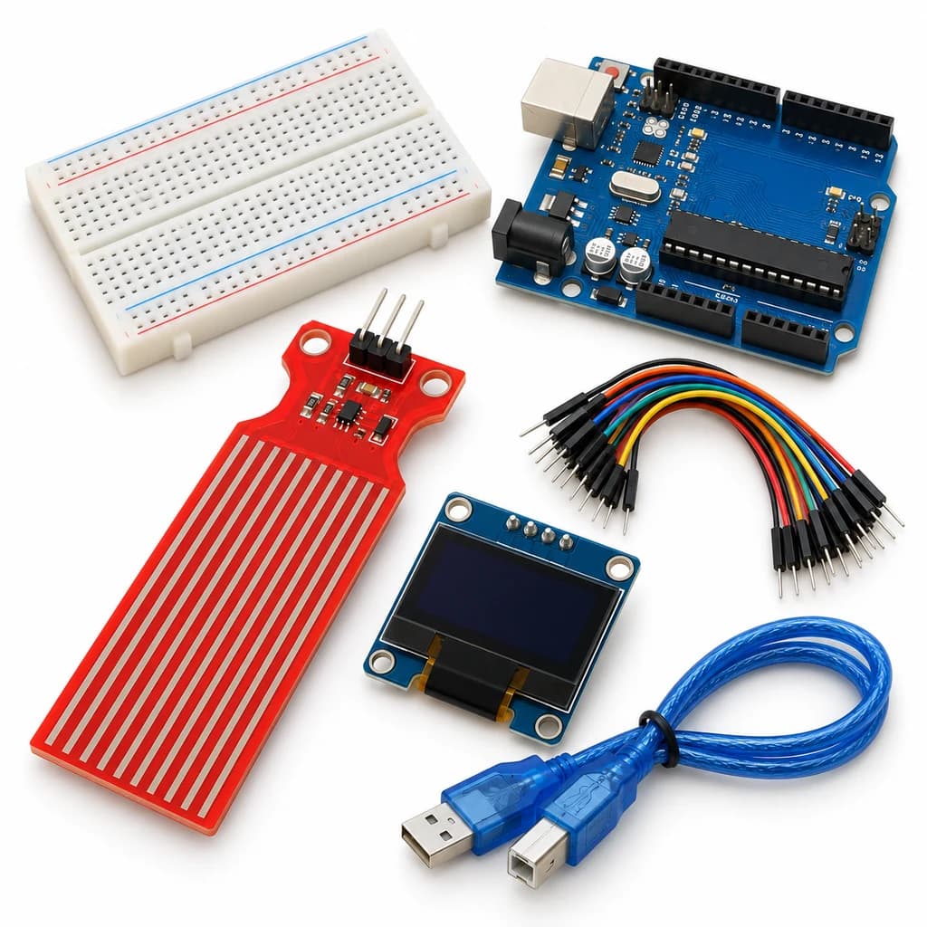 TechyTron
Water Level Display Kit
₹776.00Earn 7 pointsShop Related by product name
Related by product name
10 catalogue products Motor Drivers
AC Light lamp dimming LED lamp and 2 Channel motor Dimmer Module
₹1,177.50Earn 11 points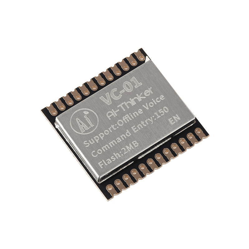 Voice Recognition Modules
Ai-Thinker VC-01 Offline Speech Recognition Module
₹298.50Earn 2 points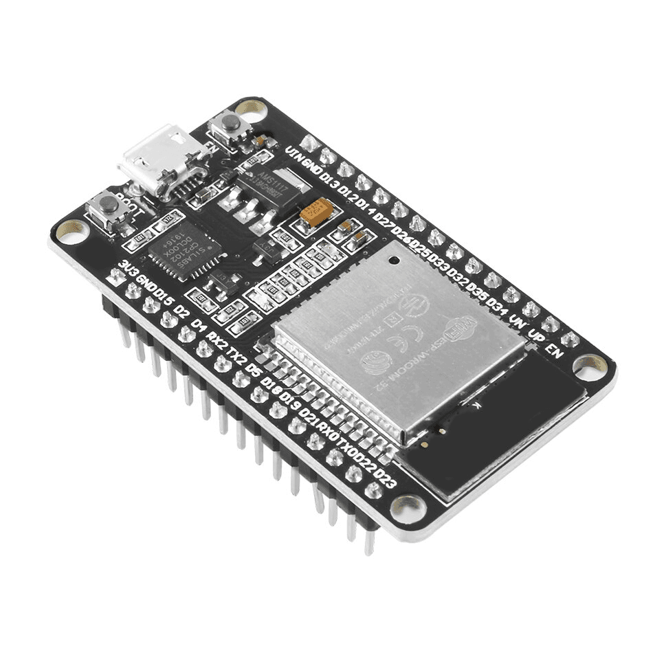 Boards
ESP32 WiFi Bluetooth BLE Development Board 30 Pin
₹395.50Earn 3 points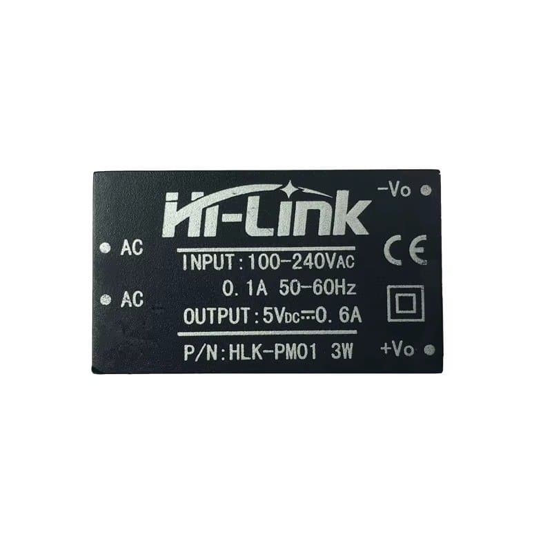 Batteries, Power Supplies & Accessories
Hi-Link HLK-PM01 5V 3W AC-DC Isolated Power Supply Module
₹259.50Earn 2 points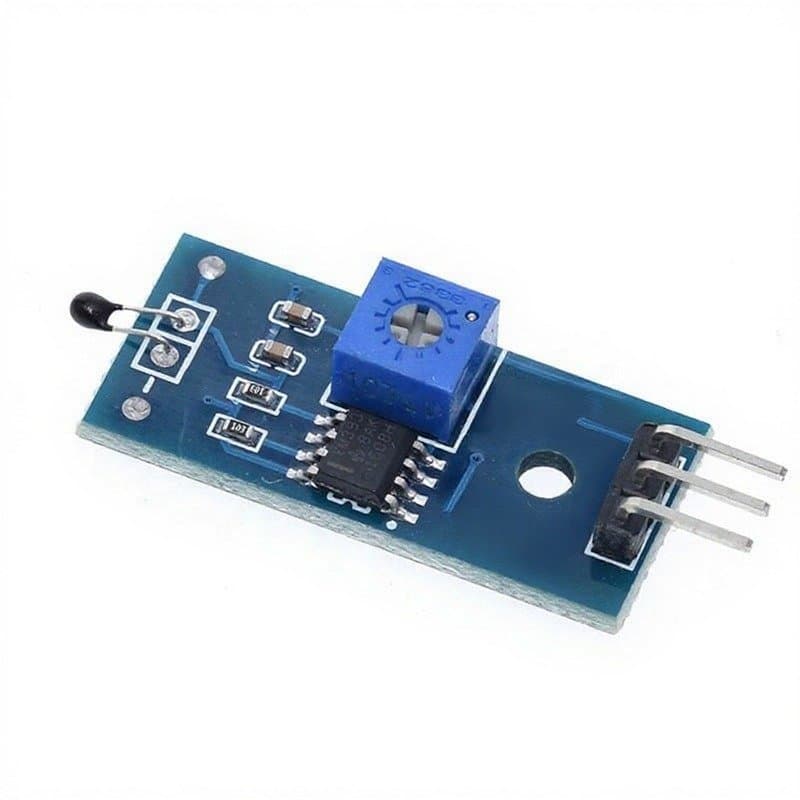 Components
NTC Thermistor Temperature Sensor Module
₹34.00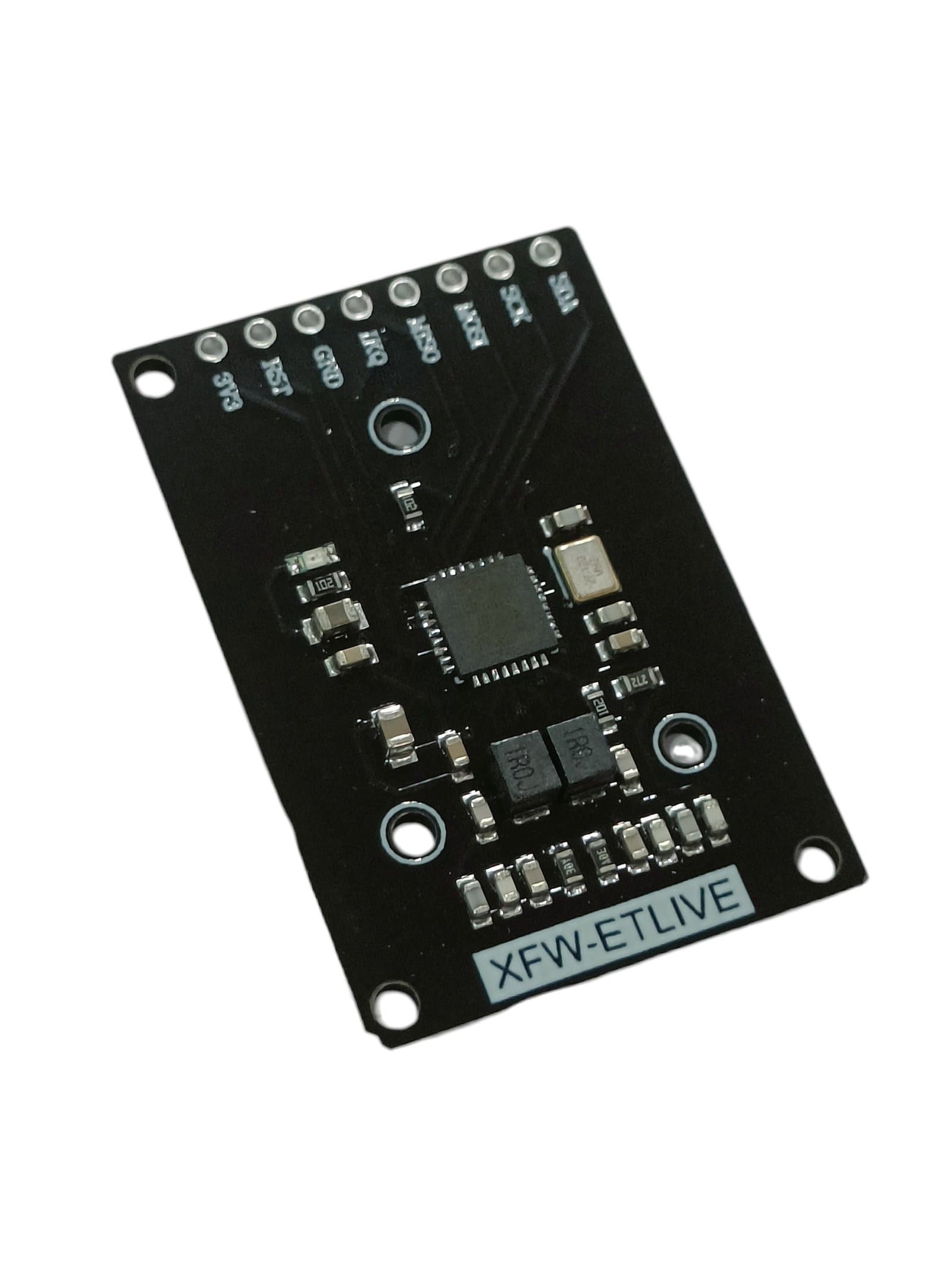 Biometric & Identification Sensors
RC522 Mini RFID 13.56MHz IC Card Reader Writer Module
₹93.00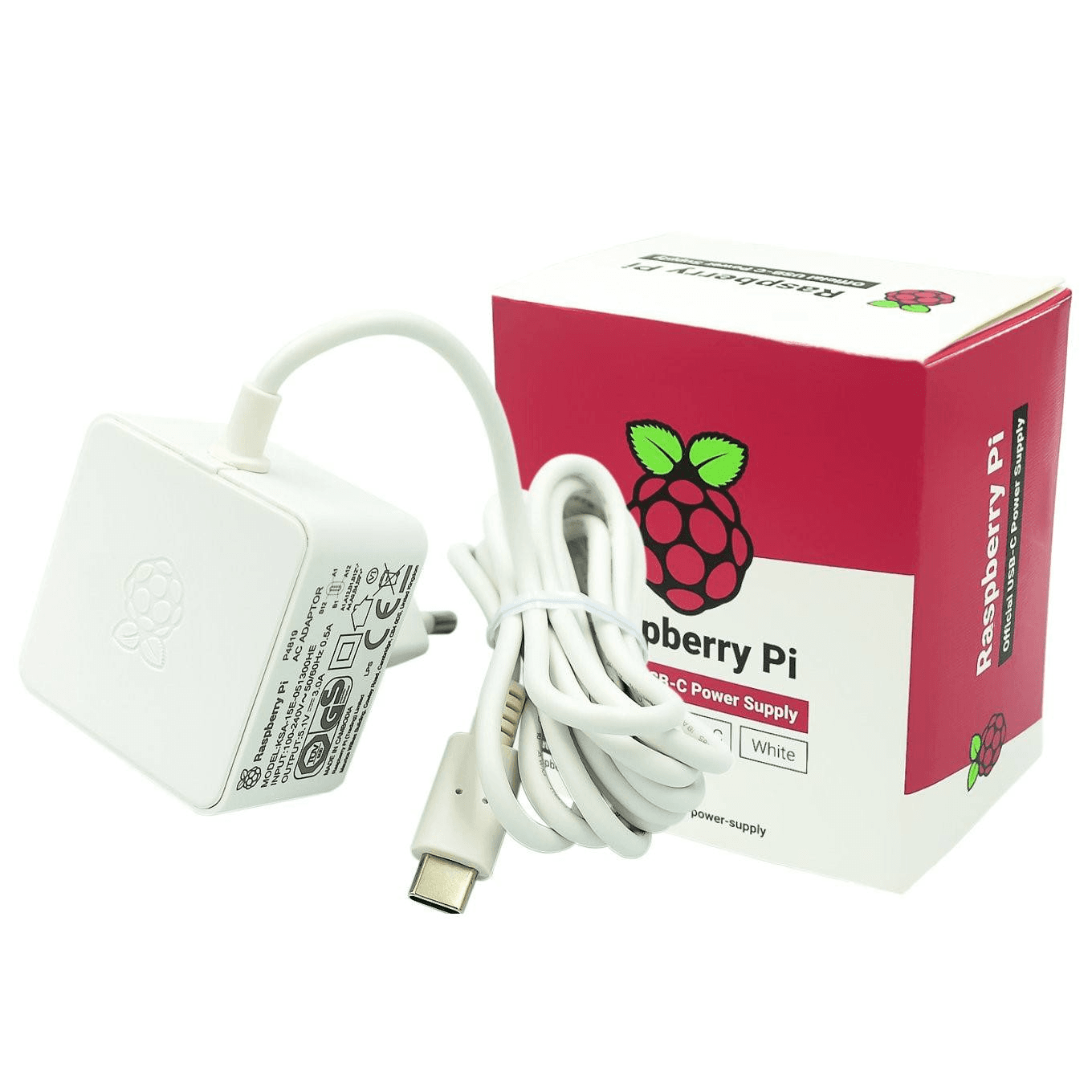 Other Raspberry Pi
Raspberry Pi 4 Official 15W USB C Power Supply
₹737.50Earn 7 points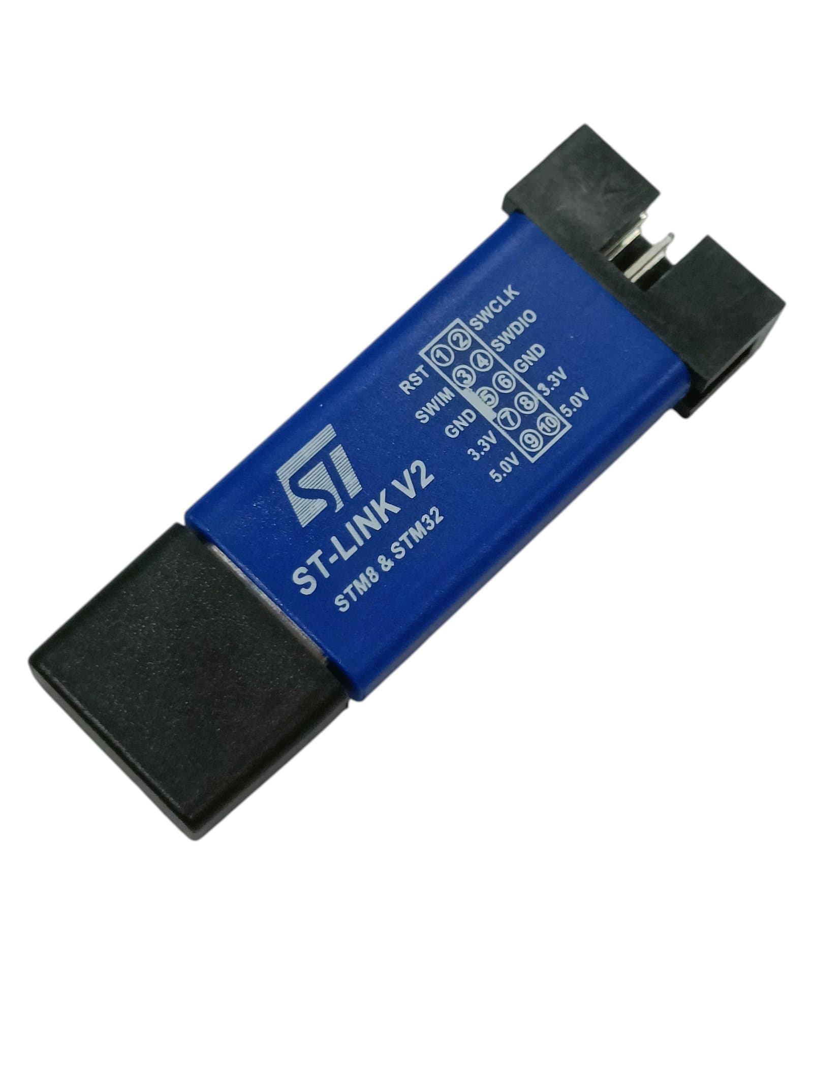 Board Support
ST-Link V2 Mini STM8 STM32 Simulator Downloader Programmer
₹171.00Earn 1 points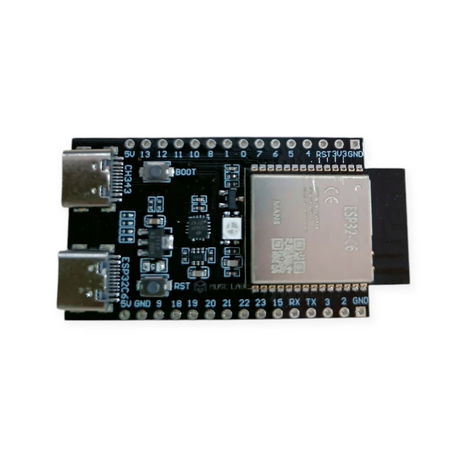 Boards
nanoESP32-C6 N8 ESP32 C6 Development Board with Wi-Fi 6, BLE 5, Zigbee, Thread and Dual USB Type-C
₹938.00Earn 9 points Other Raspberry Pi