
 TechyTron
TechyTron Two-Light Challenge STEM Kit
Find out why separate circuit paths matter. Classes 3–4 · Ages 8–10 · 40–50 minutes. Coming soon.
Delivery options
Courier from ₹79.00 per order · Free above ₹999.00
Product description
For Classes 3–4, ages 8–10, with adult guidance. No coding or soldering.
Engagement: 40–50 minutes. Predict 5 min · Build both circuits 20–25 min · Compare 15–20 min.
Included components
- 4 CELL AA BATTERY HOLDER WITH SWITCH / COVER — 1 holder
- AA BATTERY — 4 batteries (1.5 V alkaline AA cells.)
- Regulated 5 V Power Supply with Short-Circuit Protection — 1 power supply (Supplied in a screw-closed enclosure with fitted leads.)
- Small Breadboard / Mini Solderless Board - 400 points — 1 breadboard
- Jumper Wire Combo - Male to Male, Male to Female and Female to Female Breadboard Connecting Wires (10 Qty Each) — 1 set (Colour-coded leads supplied with fitted connectors.)
- Illustrated Activity Guide and Observation Sheet — 1 set
- 5mm LED - Red Color — 2 LEDs (Matched low-forward-voltage red LEDs.)
- 220 Ω 1/4 Watts (10 PCS) — 2 resistors (Quantity is individual resistors supplied in this kit; the catalogue product is a 10-piece pack.)
- 2-Pin SPST ON-OFF Mini Rocker Switch - 2A 250V — 1 switch (Used only with the supplied low-voltage DC power supply.)
- Series and Parallel Circuit Connection Cards — 1 set
Steps to make it
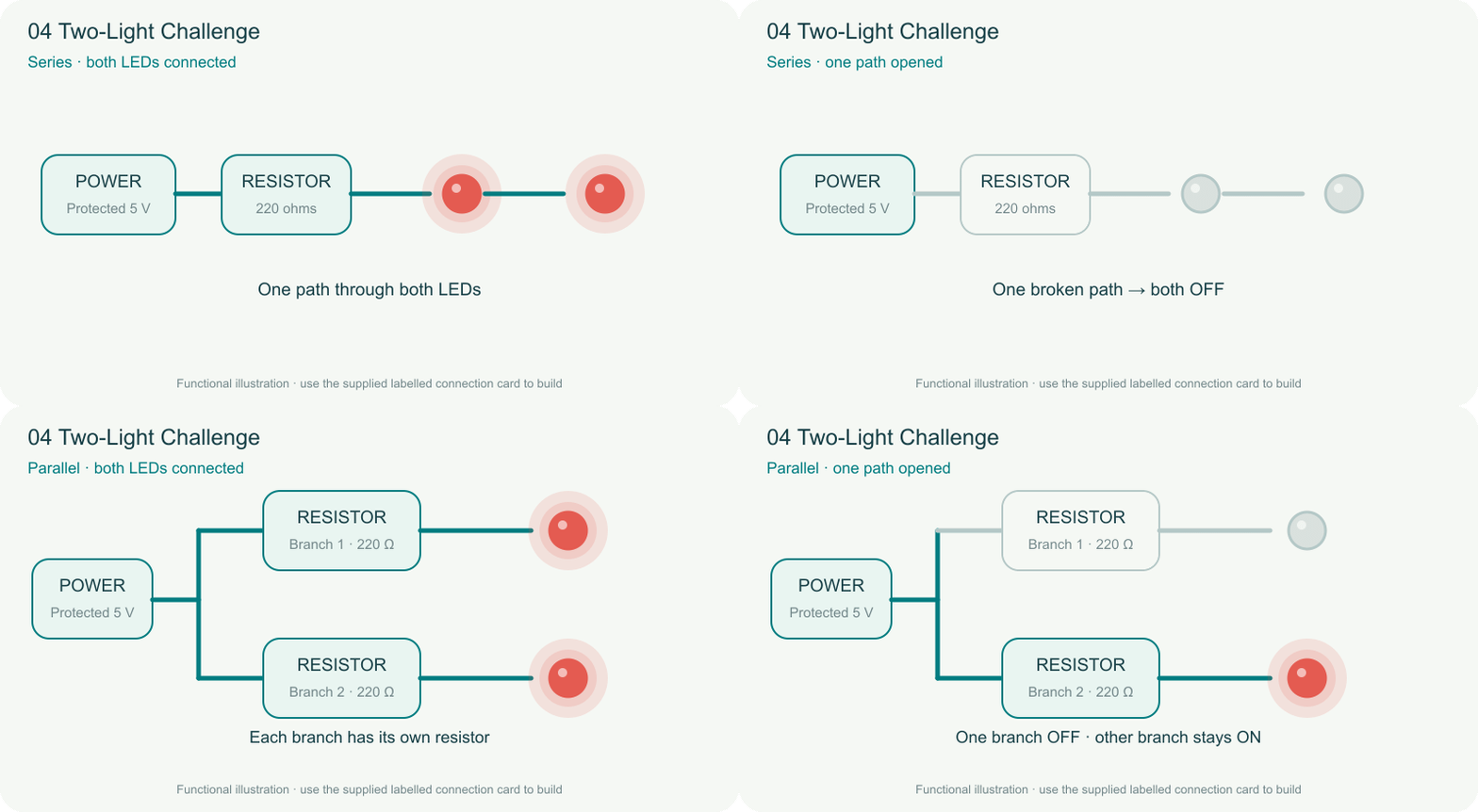
- With power off, follow Card A: power + → switch → one 220 Ω resistor → LED 1 → LED 2 → power −. Both LEDs face forward along the path.
- Turn on and observe. Turn off, open one LED connection, then turn on briefly and record what happens.
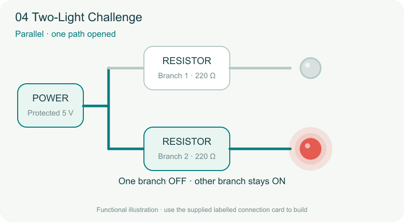
- Turn off and rebuild using Card B: after the switch, split the positive supply into two branches. Each branch contains its own 220 Ω resistor and one LED; both branches return to power −.
- Turn on and observe both LEDs.
- Turn off, disconnect just one LED branch, then turn on and observe the other branch.
What children learn
- Series components share one path.
- Parallel branches provide separate paths.
- Each parallel LED branch needs its own current-limiting resistor.
Test challenge
When one LED connection is opened, does the other LED remain on in each arrangement?
Observation task
Draw one-path and two-path circuits. Record the second LED state after one branch is opened.
Expected result
Opening the series path turns both LEDs off. Opening one parallel branch leaves the other working. Series LEDs may look dimmer.
Troubleshooting
This 5 V design requires the supplied matched red LEDs. Substituting blue or white LEDs may prevent the series pair from lighting.
Try next
Add a switch to just one parallel branch and explain why it does not control the other branch.
Use and supervision
Use only the supplied low-voltage power unit. Switch power off before changing connections. Keep metal objects across the test gap only, never across the battery terminals. Keep liquids away. Adults handle battery access and inspect parts. Kit 8 uses an enclosed motor indicator, not an exposed propeller. Use the buzzer at a comfortable level away from ears.
See how it works
Download the illustrated activity guide
Coming soon. Timing is estimated for guided first use. Illustrations show the learning principle; supplied assemblies are subject to final validation.
Customer feedback
Reviews
No published reviews yet. Be the first to share useful feedback.
Shop Related in this category
Related in this category
9 catalogue productsTechyTron TechyTron
 Brightness Lab STEM Kit
 TechyTron
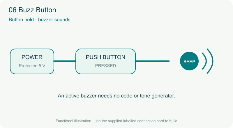
 Buzz Button STEM Kit
 TechyTron
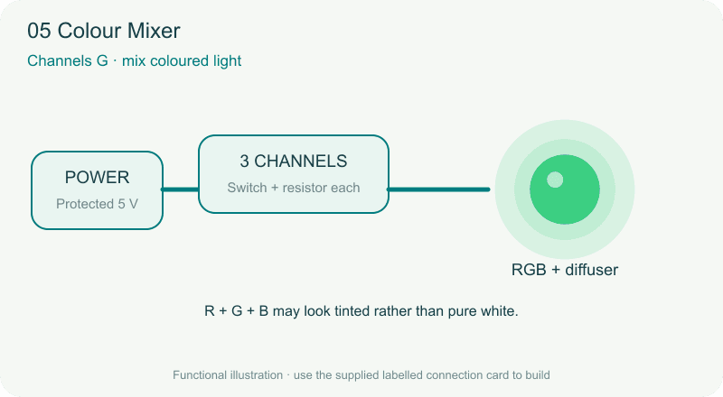
 Colour Mixer STEM Kit
 TechyTron
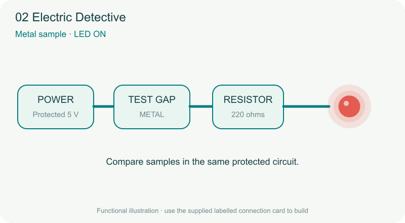
 Electric Detective STEM Kit
 TechyTron
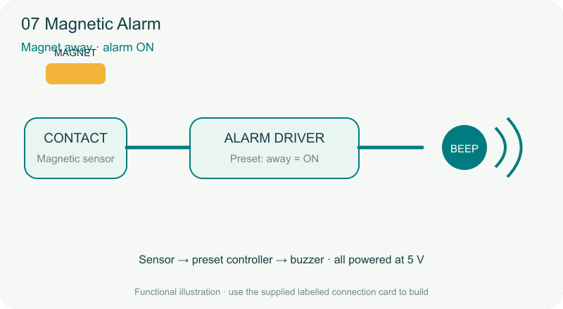
 Magnetic Alarm STEM Kit
 TechyTron
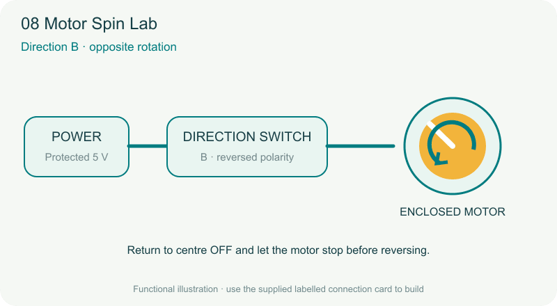
 Motor Spin Lab STEM Kit
 TechyTron
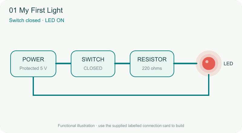
 My First Light STEM Kit
 TechyTron
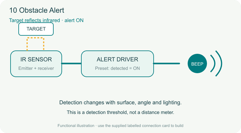
 Obstacle Alert STEM Kit
Shop Related by product name